Form No. 3383-389 Rev A 18in Turf Seeder Model No. 23511—Serial No. 314000001 and Up Model No. 33511—Serial No. 314000001 and Up Register at www.Toro.com.
WARNING CALIFORNIA Proposition 65 Warning This product contains a chemical or chemicals known to the State of California to cause cancer, birth defects, or reproductive harm. The engine exhaust from this product contains chemicals known to the State of California to cause cancer, birth defects, or other reproductive harm. Figure 1 1. Location of the model and serial numbers This spark ignition system complies with Canadian ICES-002. Model No.
Contents Safety Introduction .................................................................. 2 Safety ........................................................................... 3 Safe Operating Practices........................................... 3 Slope Indicator ....................................................... 5 Safety and Instructional Decals ................................. 6 Setup ............................................................................ 9 Unfolding the Handle .........
Operation • Watch for ditches, holes, rocks, dips, and rises that change the operating angle, as rough terrain could overturn the machine. • Never run an engine in an enclosed area. • Only operate in good light, keeping away from holes and • Always avoid sudden starting or stopping on a slope. hidden hazards. If tires lose traction, disengage the cutting blades and proceed slowly off the slope. • Start the engine only from the operator’s position.
Slope Indicator G011841 Figure 3 This page may be copied for personal use. 1. The maximum slope you can safely operate the machine on is 20 degrees. Use the slope chart to determine the degree of slope of hills before operating. Do not operate this machine on a slope greater than 20 degrees. Fold along the appropriate line to match the recommended slope. 2. Align this edge with a vertical surface, a tree, building, fence pole, etc. 3. Example of how to compare slope with folded edge.
Safety and Instructional Decals Safety decals and instructions are easily visible to the operator and are located near any area of potential danger. Replace any decal that is damaged or lost. 93–7321 1. Warning—stay away from moving parts; keep all guards in place. 125–3897 1. Warning-stay away from moving parts; keep all guards and shields in place. 119-4655 125–3917 1. Seeder On 2.
127–4061 1. Cutting blades 4. Hold the handle to start the engine. 2. Fast 5. Release the handle to stop the engine. 3. Slow 125–3809 1. Warning—read the Operator’s Manual. 5. Thrown object hazard—keep bystanders away from the machine. 2. Warning—do not operate this machine unless you are trained. 6. Warning—stop the engine before walking away from the machine. 3. Thrown object hazard—stop the engine and remove any 7. Warning—stop the engine and disconnect the spark plug wire debris from your path.
116–8537 117–4979 1. Entanglement hazard, belt—keep away from moving parts; keep all guards and shields in place.
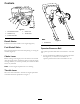
Setup Product Overview 2 Unfolding the Handle 1 1. Raise the handle to the operating position (Figure 4). 3 4 5 8 7 6 g023003 Figure 5 1 1. Operator presence bail g023004 Figure 4 2. Slide the oval locking rings down each side of the upper handle over the lower handle (Figure 4), locking the handle sections together. Checking the Engine-Oil Level The machine comes from the factory with oil in the engine crankcase; however, you may need to add oil. Refer to Changing the Engine Oil (page 17).
Controls G023178 Figure 6 1. Recoil-starter handle 2. Sediment cup 4. Choke lever 5. Throttle lever 3. Fuel-shutoff valve Figure 7 Recoil-Starter 1. Throttle lever Pull the recoil-starter handle to start engine (Figure 6). Fuel-Shutoff Valve Operator-Presence Bail Close the fuel-shutoff valve when transporting or storing the machine (Figure 6). The operator-presence bail allows the machine to start and run. • To start the machine, hold down the operator-presence Choke Lever bail (Figure 8).
Depth-Control Lever The depth-control lever allows you to set the depth of the cutting blades in 10 cutting positions along with 1 position for transportation. To adjust the depth, remove the hairpin cotter, pull the locking pin out, and move the lever forward or rearward to the desired depth setting (Figure 9). Important: Do not pull the lever side to side as this will bend it. 1 2 4 3 g019441 Figure 9 1. Depth-control lever 3. Hairpin cotter 2. Transport-position hole 4.
Specifications Note: Specifications and design are subject to change without notice. Width 70 cm (27.5 inches) Length (operating) 130 cm (51 inches) Length (with handle stored) 96.5 cm (38 inches) Height (operating) Height (with handle stored) Figure 10 Weight Refer to the seeding graph located on the machine to determine the correct gauge setting for the type of grass you are planting and the thickness in which you want to plant it. 94 cm (37 inches) 63.
Operation 1 2 3 Note: Determine the left and right sides of the machine from the normal operating position. Checking the Engine-Oil Level Service Interval: Before each use or daily 5 1. Stop the machine on a level surface. 4 Note: To ensure a more accurate measurement, adjust the depth control lever until the engine is also level. 2. Disengage the cutting blades, stop the engine, wait for all moving parts to stop, and turn off the engine switch. 3.
Using Stabilizer/Conditioner • Do not store fuel either in the fuel tank or fuel containers • over the winter unless a fuel stabilizer is used. Do not add oil to gasoline. Use a fuel stabilizer/conditioner in the traction unit to keep gasoline fresh during storage of 90 days or less. For longer storage drain the fuel tank. DANGER Important: Do not use fuel additives containing methanol or ethanol. In certain conditions, gasoline is extremely flammable and highly explosive.
Operating the Machine Note: A warm or hot engine may not require choking. 3. Hold down the operator presence bail with one hand. 1. Move the depth control lever to the desired setting. 4. Pull the recoil handle sharply to start the engine. 2. Start the engine. 5. After the engine starts, gradually move the choke to the right. 3. Push down on the handle to raise the front wheels off the ground. Note: If the engine stalls or hesitates, move the choke left again until the engine warms up. 4.
Maintenance Recommended Maintenance Schedule(s) Maintenance Service Interval Maintenance Procedure After the first 25 hours • Change the engine oil. Before each use or daily Check the engine-oil level. Clean debris form the machine. Inspect the air cleaner elements. Check the belt tension. If the engine is working but the cutting blades seem underpowered, check the belt tension. • Check the cutting blades for wear or damage. • Check the blades for wear or damage. • Check for loose fasteners.
Engine Maintenance 10. Clean the foam element in warm, soapy water or in a nonflammable solvent. Note: Do not use gasoline to clean the foam element because it could create a risk of fire or explosion. Servicing the Air Cleaner Service Interval: Before each use or daily—Inspect the air cleaner elements. Every 50 hours—Clean the air filter elements. Clean them more frequently in dusty operating conditions. Every 300 hours/Yearly (whichever comes first)—Replace the paper air cleaner element.
2. Disconnect the wire from the spark plug. 2. Disconnect the wire from the spark plug. 3. Raise the front wheels a few inches off the ground, and place a pan under the drain plug to catch the oil. 3. Move the fuel shutoff valve to the Off position. 4. Remove the sediment cup and O-ring (Figure 19). 4. Remove the drain plug (Figure 18). 1 G019428 2 Figure 18 g020282 Figure 19 1. Drain plug 1. O-ring 5.
Belt Maintenance Checking the Belt Tension Service Interval: Before each use or daily—Check the belt tension. If the engine is working but the cutting blades seem underpowered, check the belt tension. 1. Stop the machine on a level surface, stop the engine by releasing the operator presence bail, disconnect the spark-plug wire, and raise the cutting blades to the transport position. Figure 20 1. Center electrode insulator 2. Side electrode 3. Air gap (not to scale) 2.
Adjusting the Belt Tension Maintaining the Cutting Blades 1. To tighten the belt, loosen the 4 mounting nuts securing the engine to the frame. Inspecting the Cutting Blades Service Interval: Before each use or daily—Check the cutting blades for wear or damage. When the cutting blades are worn down and are no longer functioning properly; refer to Replacing Worn Cutting Blades (page 20). Important: Perform this procedure when the fuel tank is empty or nearly empty.
Figure 23 1. Bolt 5. Spacer 2. Bearing 6. Shaft 3. Washer 4. Blade 7. Nut 8. Loosen and remove the nut and washer from the shaft (Figure 23). 9. Slide the spacer off the shaft (Figure 23). 10. Carefully slide the blades off of the shaft (Figure 23) and replace them as necessary. 11. Reverse this procedure to install the assembly.
Storage 5. Check the engine oil level; refer to Checking the Engine-Oil Level (page 13). 1. Raise the cutting blades, stop the machine, stop the engine, and disconnect the spark plug wire. 6. Fill the fuel tank with fresh gasoline; refer to Filling the Fuel Tank (page 14). 2. Remove dirt and grime from the entire machine. 7. Connect the wire to the spark plug. Important: You can wash the machine with mild detergent and water. Do not pressure wash the machine.
Notes: 23
SWS Turf Renovation and Tree Care The Toro Warranty A limited warranty (see warranty periods below) Conditions and Products Covered The Toro Company and its affiliate, Toro Warranty Company, pursuant to an agreement between them, jointly warrant your Toro Products listed below to be free from defects in materials or workmanship. This warranty covers the cost of parts and labor, but you must pay transportation costs.