
Operator's Manual
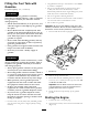
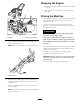
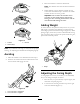
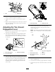

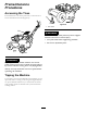
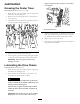
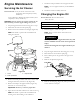

Figure17
1.Nuts2.Wheelstop
3.Raisethewheelstoptoincreasethecoringdepthand
lowerittoreducethedepthasrequired.
4.Tightenthenutssecurelytolockthewheelstopin
place.
5.Repeatsteps2through4forthewheelstopontheleft
sideofthemachine.Setthewheelstopstothesame
heightoneachside.
AdjustingtheTineGround
EngagementLever
1.Raisethetines,stopthemachine,stoptheengine,and
disconnectthesparkplugwire.
2.Thewheelarmandthepivotshaftassemblyshould
havesurface-to-surfacecontact(Figure18).Ifnot,
checkthedistanceofthelowerliftlinkageandadjust
ifnecessary.
Figure18
1.Pivotshaftassembly
3.Wheelarmassembly
2.12cm(4.8inches)
3.Thelowerballjointboltontheupperlinkrodshould
beinlinewiththehandlepivotbolt(Figure19).Ifnot,
loosenthelocknutsontheliftlinkstrapballjoints,
adjustasnecessary,andtightenthelocknuts.Care
shouldbetakentoadjusttheupperandlowerball
jointsevenly.
Figure19
1.Lowerball-jointbolt2.Handlepivotbolt
4.Checkthedistancebetweenthetineground
engagementleverandtheself-propeldrivebailas
showninFigure20.
Note:Thedistanceshouldbeapproximately38-44
mm(11/2–13/4inches);ifitisnot,thenproceedto
step5.
Figure20
1.Handle4.Tinegroundengagement
lever
2.Self-propel-drivebail
5.Jamnut
3.38to44mm(11/2to1
3/4inches)
6.Linkrod
5.Loosenbothjamnutsonbothendsofthelinkrod
nexttotheballjoints.
6.Turnthelinkroduntiltheproperdistanceisreached.
7.Tightenbothjamnutsonthelinkrodnexttotheball
joints.
15