Form No. 3323-560 CCR Powerlite Snowthrower Model No. 38173—200000001 and Up Model No.
Contents Introduction . . . . . . . . . . . . . . . . . . . . . . . . . . . . . . . . . Safety . . . . . . . . . . . . . . . . . . . . . . . . . . . . . . . . . . . . . . General Snowthrower Safety . . . . . . . . . . . . . . . . . Toro Snowthrower Safety . . . . . . . . . . . . . . . . . . . Sound Pressure Level . . . . . . . . . . . . . . . . . . . . . . . Sound Power Level . . . . . . . . . . . . . . . . . . . . . . . . Vibration Level . . . . . . . . . . . . . . . . . . . . . . . . . . . .
• Use only the power cord supplied with the snowthrower and a receptacle appropriate for use with the cord for electric starting motors. understand the contents of this manual before the motor is ever started. Pay particular attention to the safety alert symbol which means CAUTION, WARNING, OR DANGER — “personal safety instruction.” Read and understand the instruction because it has to do with safety. Failure to comply with instruction may result in personal injury.
• Never operate the snowthrower near glass enclosures, automobiles, window wells, drop-offs, etc. without proper adjustment of the snow discharge angle. Keep children and pets away. operating the snowthrower. Keep your face hands, feet, and any other part of your body or clothing away from concealed, moving, or rotating parts.
Sound Pressure Level Vibration Level This unit has a sound pressure at the operator’s ear of 90 dB(A), based on measurements of identical machines per Directive 81/1051/EEC. This unit has a maximum hand-arm vibration level of 11.4 m/s2, based on measurements of identical machines per EN 1033. Sound Power Level This unit has a sound power level of 103 LwA, based on measurements of identical machines per Directive 79/113/EEC.
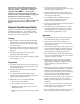
Shut off engine and remove key before leaving operator position – two stage snowthrower Cutting or entanglement of foot – rotating auger Severing of fingers or hand – impeller blade Electric start Hot surfaces – burns to fingers or hands Machine loss of control – uphill slope Caustic liquids – chemical burns to fingers or hands Machine loss of control downhill slope Do not tip battery Traction drive Keep dry Snowthrower collector auger Machine travel direction – forward Engage Machine travel d
On/start Choke Off/stop Engine speed (Throttle) Fast Neutral Slow Snowthrower collector auger/impeller Decreasing/Increasing Lock Engine start Unlock Engine stop Lever operation Snowthrower chute direction Lever operation 7
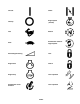
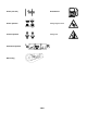
Primer (start aid) Unleaded fuel Primer operation Cutting of fingers or hand Throttle operation Cutting of foot PowerShift operation Belt routing 8
Assembly Note: Determine the left and right sides of the snowthrower by standing in the normal operating position. Loose Parts DESCRIPTION QTY. Hex bolts 2 Locknuts 2 Washers 2 Discharge chute 1 Upper handle 1 Knobs 2 Oval head bolts 2 Curved washers 2 Spring 1 Spring cover 1 Cable adjuster 1 Control cable 1 USE Installing the discharge chute Installing the handle Installing the control cable Installing the Discharge Chute 2 4 1.
Installing the Handle 5 1. Position the ends of the upper handle on the inside of the lower handles and align the holes (Fig. 3). Ensure that the handle is positioned so that the control bar is on the upper side of the handle. 4 6 1/16-1/8” 2. Secure the upper handle to the lower handle using oval head bolts, curved washers, and knobs (Fig. 3). 3 3. Position the knobs and curved washers on the inside of the handle and tighten the knobs securely.
7. Ensure that a 1/16 to 1/8 inch (0.16 to 0.32 cm) gap exists between the control bar and the handle (Refer to the inset in Fig. 4). To adjust this gap, refer to Adjusting the Control Cable on page 15. DANGER POTENTIAL HAZARD • When fueling, under certain circumstances, a static charge can develop, igniting the gasoline. IMPORTANT: The control cable must contain slack when it is in the disengaged position.
2 1 2 1 3 3 5 111 Figure 6 1. Add oil to small amount of gasoline 2. Install cap and shake can to mix 6 3. Add remaining amount of gasoline 4 919 Figure 7 1. 2. 3. 4. We recommend using a fuel stabilizer/conditioner for all Toro gasoline-powered products during operation and storage. A fuel stabilizer/conditioner cleans the engine during operation and prevents gum-like varnish deposits from forming in the engine during storage.
Run the electric starter no more than 10 times at intervals of 5 seconds on, then 5 seconds off. If the engine does not start after this attempt, wait at least 40 minutes to allow the starter to cool before attempting to start it again. 2 1 IMPORTANT: Running the electric starter extensively can overheat and damage the starter. 3 If the engine does not start after the second attempt, bring the snowthrower to an Authorized Service Dealer for service. m-3371 C.
• In snowy and cold conditions, some controls and moving parts may freeze solid. Do not use excessive force when trying to operate frozen controls. If you have difficulty operating any control or part, start the engine and let it run for a few minutes. 1. Remove the locknut and washer from the rear of the discharge chute (Fig. 2). 2. Fold the chute down and install the locknut and washer tightly onto the bolt at the rear of the discharge chute handle (Fig. 9).
CAUTION POTENTIAL HAZARD • If you leave the wire on the spark plug, someone could start the engine. WHAT CAN HAPPEN • Accidental starting of engine could seriously injure you or other bystanders. HOW TO AVOID THE HAZARD • Pull the wire off of the spark plug before you do any maintenance. Also, push it aside so it does not accidentally contact the spark plug. Adjusting the Control Cable moisture, start the rotor and operate it without a load for 30 seconds.
Replacing the Drive Belt Inspect the drive belt before each season, and replace it if it is worn or damaged. 1. Stop the engine and remove the key from the switch. 5 2. Pull the wire off the spark plug. 3 2 4 3. Remove three self-tapping screws, one capscrew, one washer, and one nut that secures the left side cover to the snowthrower frame (Fig. 11). 6 1 m–4014 Figure 13 1. Rotor pulley 2. Drive pulley 3. Idler pulley 1 2 7. Remove the drive belt from the rotor pulley (Fig. 13). 925 8.
Replacing the Rotor Blades Before each snowy season, inspect the rotor blades for wear. When a rotor blade edge has worn to the wear indicator hole (Fig. 16), replace both rotor blades to ensure proper performance and to prevent damage to the underside of the snowthrower. 1 2 917 1 Figure 14 1. Control panel 2. Screws 2. Remove the ignition key and lift off the panel, allowing it to hang on the recoil rope. Figure 16 3. Pull the wire off the spark plug and remove the spark plug (Fig. 15) 1.
4. Position the screw heads on the thick layer side of the blade (Fig. 17). 6. Tighten all screws and nuts securely. 7. Repeat steps 1 through 6 above to replace the other blade. 5. Curve the blade and secure it with the remaining four torx screws and locknuts, positioning the screw heads on the thick layer side of the blade (Fig. 17). 8 2 1 4 5 1 3 7 1 1 6 Figure 17 1. 2. 3. 4. Torx screw Capscrew Locknut Blade support 5. 6. 7. 8.
Covering and Storing the Snowthrower WARNING POTENTIAL HAZARD • Gasoline is highly flammable, explosive, and dangerous if inhaled. WHAT CAN HAPPEN • If gasoline contacts a flame or is inhaled, serious personal injury an occur. HOW TO AVOID THE HAZARD • Never store the snowthrower in a house (living area) or a basement where ignition sources may be present, such as hot water and space heaters, clothes dryers. • Allow the engine to cool before storing the snowthrower in an enclosure.