
Operator's Manual


15
929
8
7
5
6
1
4
3
2
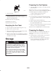
Figure 11
1. Torx screw (4 per rotor
blade)
2. Bolt (2 per rotor blade)
3. Locknut (6 per rotor
blade)
4. Blade support (2)
5. Wear indicator hole
6. Drive belt cover
7. Thin layer of rotor blade
8. Thick layer of rotor blade
5. Slide the old rotor blade out from between the blade
supports (Fig. 11).
6. Examine a new rotor blade edge for the difference in
layer thickness (Fig. 11).
Note: Install the rotor blades with the thick layer on the
inside of the curve. (Fig. 11). If you do not install the
blades properly, the blades will be out of balance and
cause the snowthrower to “hop” or “bounce.”
7. Insert a new rotor blade between the blade supports.
8. Secure the center of the rotor blade to the blade
supports with two bolts and two locknuts.
9. Position the screw heads on the thick layer side of the
rotor blade (Fig. 11).
10. Curve the rotor blade and secure it with the remaining
four torx screws and locknuts, positioning the screw
heads on the thick layer side of the rotor blade (Fig. 11).
11. Tighten all screws and locknuts securely.
12. Repeat steps 4 through 11 above to replace the other
rotor blade.
13. Connect the wire to the spark plug.
14. Install the control panel.
15. Insert the key in the switch.
Replacing the Drive Belt
Inspect the drive belt before each season, and replace it if it
is worn or damaged.
1. Stop the engine and wait for all moving parts to stop.
2. Remove the key from the switch.
3. Disconnect the wire from the spark plug. Refer to steps
3 through 5 of Replacing the Spark Plug on page 16.
4. Remove two short self-tapping screws, one long
self-tapping screw, one bolt, one washer, and one nut
that secure the left side cover to the snowthrower frame
(Fig. 12).
1
925
2
3
Figure 12
1. Bolt, nut, and washer
2. Short self-tapping screws
3. Long self-tapping screw
5. Remove the cover.
6. Loosen the four engine mounting nuts enough to allow
the belt guide to rotate away from the drive pulley
(Fig. 13).
m–4015
2
3
4
5
1
7
6
Figure 13
1. Brake arm
2. Idler pulley
3. Idler spring
4. Hole
5. Engine mounting nuts
(3 of 4 shown)
6. Cable pulley
7. Belt guide
Important Removing the nuts will cause the engine to
become loose.
7. Loosen the idler pivot nut (Fig. 14).