
Operator's Manual


8
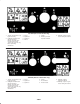
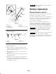
Installing the Handle
1. Position the ends of the upper handle section on the
inside of the lower handle section and align the holes
(Fig. 2).
m–4022
1
5
2
4
3
Figure 2
1. Handle knob (2)
2. Lower handle section
3. Oval-head bolt (2)
4. Upper handle section
5. Curved washer (2)
2. Insert the oval-head bolts into the aligned holes in the
handle sections with the bolt heads on the outside of the
handle (Fig. 2).
3. Install the curved washers and the handle knobs on the
oval-head bolts and tighten the handle knobs securely.
Note: Ensure that the oval-head bolts and the curved
washers are properly installed (See inset in Fig. 2).
Installing the Discharge Chute
1. Position the holes in the sides on the discharge chute
over the hex bolts on the sides of the chute handle
(Fig. 3).
m-3371
1
2
4
5
3
4
Figure 3
1. Discharge chute
2. Hex bolt (3)
3. Chute handle
4. Washer (3)
5. Locknut (3)
2. Secure the discharge chute onto the hex bolts with two
washers and two locknuts (Fig. 3).
3. Hold the hex bolt heads with a wrench and tighten the
locknuts securely.
4. Rotate the discharge chute to the upright position.
5. Install the locknut and the washer tightly onto the screw
at the rear of the discharge chute (Fig. 3).
Installing the Control Cable
Important When you install the control cable to the
upper handle, ensure that the cable is in the groove of the
cable pulley on the lower left side of the snowthrower (Fig.
13).
1. Route the control cable through the loop on the left side
of the snowthrower (Fig. 4).