
Operator's Manual

5
3329-440 Rev A
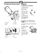
Product Overview
m-6238a
1
2
3
4
5
6
7
1. Discharge chute
2. Chute handle
3. Control bar
4. Handle
5. Control panel
6. Rotor blade
7. Fuel tank cap
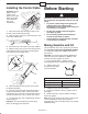
1
2
3
4
m-6240
1. Choke lever
2. Key switch
3. Primer
4. Recoil starter
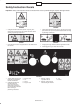
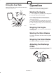
Setup
Installing the Handle
1. Position the ends of
the upper handle on the
inside of the lower
handle and align the
holes.
2. Insert the oval-head
bolts into the aligned
holes, with the bolt
heads on the outside of
the handle.
3. Install the curved
washers and the handle
knobs on the oval-head
bolts and tighten the
knobs securely.
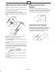
Installing the Discharge
Chute
1. Position the holes in the sides of the discharge
chute (A) over the bolts ends (B) on the sides of the
chute handle.
2. Secure the sides of
the discharge chute with
2 washers and 2
locknuts.
3. Rotate the
discharge chute to the
upright position.
4. Install the washer
and locknut (C) tightly
onto the bolt end at the
rear of the discharge
chute.
A
B
C
m6678