
Operator's Manual
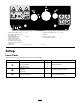
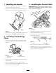
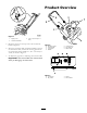
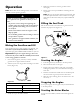
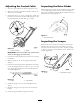
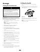

Figure 7
1. Spring cover
3. 1/16 to 1/8 inch (2 to 3
mm)
2. Control bar bracket
5. Hook the spring into the top hole of the control bar
brac k et ( Figure 7 ).
6. Mo v e the control bar bac k to w ard the handle to remo v e
the slac k in the cable , and ensure that the g ap betw een
the control bar and the handle is 1/16 to 1/8 inc h (2 to
3 mm) as sho wn in Figure 7 .
7. T o adjust this g ap , refer to Adjusting the Control Cable .
Important: T he contr ol ca ble must contain slack
when y ou disenga ge the contr ol bar .
Product Overview
Figure 8
1. Discharge chute 5. Control panel
2. Chute handle 6. Fuel tank cap
3. Control bar 7. Rotor blade
4. Handle
Figure 9
1. Choke lever
3. Primer
2. Key switch 4. Recoil starter
6