
Operator's Manual
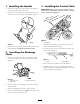
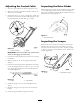

Adjusting the Control Cable
1. Stop the engine and w ait for all mo ving par ts to stop .
2. Mo v e the control bar to w ard the handle to remo v e the
slac k in the control cable .
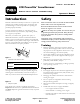
3. Ensure that there is a 1/16 to 1/8-inc h (2 to 3 mm) g ap
betw een the control bar and the handle ( Figure 13 ). If
y ou m ust adjust the control cable , g o to ste p 4 .
Figure 13
1. Control bar bracket 2. Handle
Important: T he contr ol ca ble must contain slack
when y ou disenga ge the contr ol bar .
4. Unhook the spring end from the top hole in the control
bar brac k et.
5. Slide the spring co v er off the spring and the cable
adjuster .
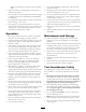
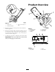
6. Unhook the Z-fitting from the cable adjuster and inser t
it into the appropriate hole to obtain a 1/16 to 1/8 inc h
(2 to 3 mm) g ap betw een the control bar brac k et and
the handle ( Figure 14 ).
Figure 14
1. Z-tting 2. Cable adjuster
7. Install the spring co v er o v er the cable adjuster and
spring .
8. Hook the spring into the top hole of the control bar
brac k et.
9. Chec k the g ap and adjust it ag ain if necessar y .
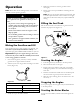
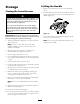
Inspecting the Rotor Blades
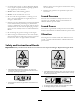
Before eac h season, inspect the rotor blades for w ear . W hen
a rotor blade edg e has w or n do wn to the w ear indicator
hole , ha v e an A uthorized Ser vice Dealer re place both rotor
blades and the scraper ( Figure 15 ).
Figure 15
1. Wear indicator hole
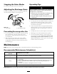
Inspecting the Scraper
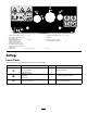
Before eac h season, inspect the scraper for w ear . If the
thic kness from the top of the w ear indicator g roo v e to
the bottom of the scraper is less than 1/16 inc h (1.6 mm)
or there is no long er a w ear indicator g roo v e , re place the
scraper ( Figure 16 ).
Figure 16
1. Scraper
2. Wear indicator groove
9