Form No. 3326-125 Rev A CCR 2450 GTS CCR 3650 GTS Snowthrower Model No. 38515—220000001 and Up Model No. 38516—220000001 and Up Model No. 38517—220000001 and Up Model No.
Warning Emptying the Fuel Tank . . . . . . . . . . . . . . . . . . . . . Storage . . . . . . . . . . . . . . . . . . . . . . . . . . . . . . . . . . . . . Preparing the Fuel System . . . . . . . . . . . . . . . . . . . Preparing the Engine . . . . . . . . . . . . . . . . . . . . . . . Preparing the Snowthrower . . . . . . . . . . . . . . . . . . Folding the Handle . . . . . . . . . . . . . . . . . . . . . . . . . Troubleshooting . . . . . . . . . . . . . . . . . . . . . . . . . . . . . .
• Exercise caution to avoid slipping or falling. This manual identifies potential hazards and has special safety messages that help you and others avoid personal injury and even death. Danger, Warning, and Caution are signal words used to identify the level of hazard. However, regardless of the hazard, be extremely careful. Preparation • Thoroughly inspect the area where you will use the snowthrower. Remove all doormats, sleds, boards, wires, and other foreign objects.
• Rotating rotor blades can injure fingers or hands. Stay behind the handles and away from the discharge opening while operating the snowthrower. Keep your face, hands, feet, and any other part of your body or clothing away from moving or rotating parts. • Stop the engine whenever you leave the operating position, before unclogging the discharge chute, and when making any repairs, adjustments, or inspections.
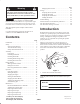
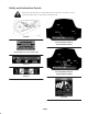
Safety and Instruction Decals Safety decals and instructions are easily visible to the operator and are located near any area of potential danger. Replace any decal that is damaged or lost.
French translation of U.S. EPA decal text: Ce moteur est conforme à la réglementation antipollution Phase EPA relative aux moteurs ULGE. Famille : XXXXX.XXXXXX Nº de modèle : XXX–XXXX CYLINDREE (CC) : 141 Pour plus de détails sur la sécurité, l’entretien et les réglages, reportez-vous au manuel de l’utilisateur.
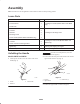
Assembly Note: Determine the left and right sides of the machine from the normal operating position. Loose Parts DESCRIPTION QTY.
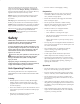
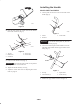
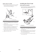
Installing the Handle Models 38517 and 38518 1. Cut the plastic tie that secures the control cable to the handle (Fig. 6). 1 m 5516 3 2 Figure 4 4. Insert the loose end of the control cable into the bottom hole in the control bar (Fig. 5). m 5536 Figure 6 1. Handle 2. Plastic tie 3. Control cable 3 1 Important If you do not cut the plastic tie, the rotor brake will not function properly. 4 5 2.
Installing the Discharge Chute Models 38515 and 38516 1. Place the discharge chute over the chute ring, and align the hole in the back of the discharge chute with the center hole in the chute ring (Fig. 10). 3 2 m 5516 Figure 8 1 4. Loosely install the handle lock, curved washer, and knob on the left side of the handle as shown in Figure 7. Note: Ensure that the curved side of the curved washer is against the handle. m 5520 5.
Models 38517 and 38518 Installing the Chute Crank 1. Place the discharge chute over the chute ring, and align the hole in the back of the discharge chute with the center hole in the chute ring (Fig. 11). Models 38517 and 38518 1. Insert the flattened end of the chute crank through the hole in the shroud while aligning the mounting bracket with the holes in the lower handle (Fig. 12). 2 3 1 1 2 m 5520 Figure 11 1. Chute ring 2. Discharge chute m 5545 2.
Before Starting Danger Mixing Gasoline and Oil When fueling, under certain circumstances, a static charge can develop, igniting the gasoline. A fire or explosion from gasoline can burn you and others and damage property. Your Toro snowthrower is powered by a two-cycle engine that requires a 50:1 gasoline-to-oil mixture. Use only clean, unleaded gasoline no more than 30 days old and with an octane rating of 87 or higher.
3. Install the cap on the fuel container. 3 2 4. Shake the container to mix the gasoline and oil thoroughly. 4 1 5. Slowly remove the cap and add the remaining amount of gasoline. Filling the Fuel Tank Important Do not overfill the fuel tank. The gasoline-and-oil mixture must have room to expand. 1. Clean around the fuel tank cap; do not allow snow or water to enter the fuel tank. 5 2.
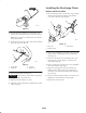
Adjusting the Discharge Chute Caution Models 38515 and 38516 If you leave the snowthrower plugged into a power outlet, someone can inadvertently start the snowthrower and injure people or damage property. Move the chute handle left and right to adjust the direction of the snow stream (Fig. 14). The chute deflector handle on top of the discharge chute controls the height of the snow stream. Unplug the power cord whenever you are not starting the snowthrower. 1 B. Push the starter button.
• In snowy and cold conditions, some controls and moving parts may freeze. Do not use excessive force when trying to operate frozen controls. If you have difficulty operating any control or part, start the engine and let it run for a few minutes. 3 1 • After clearing the snow, let the engine run for a few minutes to prevent moving parts from freezing. Shut off the engine, wait for all moving parts to stop, and remove all ice and snow from the snowthrower.
Maintenance Note: Determine the left and right sides of the machine from the normal operating position. Recommended Maintenance Schedule Maintenance Service Interval Maintenance Procedure Initially • Check the control cable both initially and after the first hour of operation; adjust it if necessary. Refer to Adjusting the Control Cable on page 16. • Check for loose fasteners and tighten them if necessary. Annually • Check the control cable and adjust it if necessary.
Adjusting the Control Cable Important The control cable must contain slack when you disengage the control bar for the rotor blades to stop properly. Check the control cable for proper adjustment initially, after the first operating hour, and then annually thereafter. Adjusting the Cable Checking the Cable For Models 38515 and 38516 only: 1. Stop the engine and wait for all moving parts to stop. 1. Unhook the spring end from the control bar (Fig. 16). 2.
drive system. To remove moisture, start the rotor and operate it without a load for 30 seconds. Once you remove the moisture, the drive belt should not slip. For Models 38517 and 38518: 1. Unhook the upper cable end from the hole in the control bar (Fig. 17). 2. Slide the spring cover up the cable to expose the cable adjuster (Fig. 19). Replacing the Rotor Blades Before each season, inspect the rotor blades for wear. When a rotor blade edge has worn down to the wear indicator hole (Fig.
Removing the Old Rotor Blades 3 1. Remove the 4 torx screws and the 4 locknuts that secure the outer edges of the rotor blade to the rotor assembly (Fig. 21). 1 2 4 1 6 4 m-5538a/m-5059 7 Figure 22 5 3 8 1. Thick rubber side 2. Wear indicator hole 4 2 3. Thin rubber side 4. Inside of curved surface 680 Install the new rotor blade with the thick rubber layer on the inside of the curved surface (Fig. 22). If you do not install the rotor blade properly, it will wear out more quickly.
2 Replacing the Scraper Note: If the rotor blades are partially or completely worn, replace the rotor blades when you replace the scraper. This ensures proper snowthrower operation and performance. 1 1. Stop the engine and wait for all moving parts to stop. m-5061a 2. Remove the key from the switch. Figure 24 3. Remove the control panel and disconnect the wire from the spark plug. Refer to steps 3 through 5 of Replacing the Spark Plug on page 19. 1. Control panel 4.
5. Pull up on the idler pulley and remove the old drive belt from the rotor pulley, the brake arm assembly, and the engine pulley (Fig. 28). 1 2 m-3215 1 Figure 26 4 1. 0.030 in. (0.76 mm) 10. Install the spark plug by hand and then torque it to 15 ft-lb (20.4 N m). If you do not have a torque wrench, tighten the plug firmly. 6 11. Connect the wire to the spark plug. 12. Install the control panel. 13. Insert the key in the switch.
5. Start the engine and run it until it stops. Danger 6. Choke or prime the engine, start it a third time, and run the engine until it will not start. Gasoline is highly flammable; it can ignite and cause serious personal injury. 7. Dispose of unused fuel properly. Recycle it according to local codes, or use it in your automobile. • • • • Drain gasoline outdoors. Drain gasoline from a cold engine only. Wipe up any gasoline that may have spilled.
Troubleshooting Toro designed and built your snowthrower for trouble-free operation. Check the following components and items carefully, and refer to Maintenance on page 15 for more information. If a problem continues, contact an Authorized Service Dealer. Problem Electric starter does not turn (electric-start models only) Engine does not start or starts hard Engine runs rough Possible Causes Corrective Action 1. The power cord is disconnected at the outlet or the snowthrower. 1.
Problem Engine runs, but the snowthrower discharges snow poorly or not at all Snowthrower does not properly clear snow off the surface Snowthrower does not self-propel Rotor blades do not stop properly Possible Causes Corrective Action 1. You are walking too fast or too slow. 1. Change your walking speed. 2. You are trying to remove too much snow per swath. 2. Reduce the amount of snow removed per swath. 3. You are trying to remove extremely heavy or wet snow. 3.
Federal Emission Control Warranty Statement A Two-Year Limited Warranty Your Warranty Rights and Obligations The U.S. Environmental Protection Agency (EPA), Toro, and Toro Warranty Company are pleased to explain the emission control system warranty on your 1997 and later utility/lawn/garden equipment engine. 1997 and later model year utility/lawn/garden equipment engines must be designed, built and equipped, at the time of sale, to meet the U.S. EPA regulations for small non-road engines.
How to Get Warranty Service General Conditions Should you feel your Toro Product requires warranty service, contact the dealer who sold you the product or any Authorized Service Dealer or Master Service Dealer. The Yellow Pages of your telephone directory is a good reference source. The dealer will either arrange service at his/her dealership or recommend another Authorized Service Dealer who may be more convenient. You may need proof of purchase (copy of registration card, sales receipt, etc.
The Toro Starting Guarantee A Five-Year Full Warranty on All Toro GTS-5 Engines Conditions and Products Covered The Toro Company and its affiliate, Toro Warranty Company, pursuant to an agreement between them, jointly guarantee that your Toro Engine will start on the first or second pull for five years from the date of purchase—if you provide the routine maintenance it requires—or we will fix it free of charge. This warranty covers the cost of parts and labor, but you must pay transportation costs.
Date Hours Used Air Cleaner Service (mowers only) Change Oil (does not apply to two-cycle) Lubricate Wheels (mowers only) Check Spark Plug Storage Preparation Part No. 374-0018 Rev.
Gas Powered Snow Products The Toro Total Coverage Guarantee A Two-Year Full Warranty (Limited Warranty for Commercial Use) Conditions and Products Covered Owner Responsibilities The Toro Company and its affiliate, Toro Warranty Company, pursuant to an agreement between them, jointly promise to repair any Toro Product used for normal residential purposes* if defective in materials or workmanship for a period of two years from the date of purchase.