
Operator's Manual


18
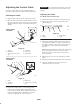
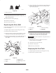
Removing the Old Rotor Blades
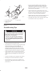
1. Remove the 4 torx screws and the 4 locknuts that secure
the outer edges of the rotor blade to the rotor assembly
(Fig. 21).
1
2
3
4
4
5
6
7
8
680
Figure 21
1. Rotor blade (2)
2. Rotor half (2)
3. Torx screw (8)
4. Locknuts (13)
5. Hex-head bolts (4)
6. Spacer (4)
7. Rotor assembly
8. Long hex-head bolt
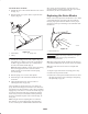
2. Remove the 2 hex-head bolts and 2 locknuts that secure
the center of the blade to the rotor halves (Fig. 21).
3. Loosen the long hex-head bolt that secures the rotor
halves to the auger shaft assembly (Fig. 21).
4. Slide the rotor blade out from between the rotor halves
(Fig. 21).
5. Remove the 2 spacers from the old rotor blade and
install the spacers in a new rotor blade.
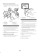
Installing a New Rotor Blade
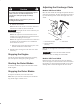
1. Examine a new rotor blade edge for the difference in
the thickness of the rubber layers (Fig. 22).
m-5538a/m-5059
1
2
3
4
Figure 22
1. Thick rubber side
2. Wear indicator hole
3. Thin rubber side
4. Inside of curved surface
Install the new rotor blade with the thick rubber layer
on the inside of the curved surface (Fig. 22). If you do
not install the rotor blade properly, it will wear out more
quickly.
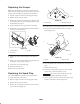
2. Ensure that the spacers are in the new rotor blade, and
insert the new rotor blade between the rotor halves.
3. Secure the new rotor blade to the rotor halves with the 2
hex-head bolts and 2 locknuts that you previously
removed. Position the bolt heads on the thick rubber
side of the rotor blade (Fig. 22).
4. Curve the new rotor blade and secure it with the torx
screws and locknuts you previously removed,
positioning the screw heads on the thick rubber side of
the rotor blade (Fig. 22).
5. Tighten all screws and locknuts securely.
6. Replace the scraper. Refer to Replacing the Scraper on
page 19.
7. Connect the wire to the spark plug.
8. Install the control panel.
9. Insert the key in the switch.