
Operator's Manual

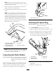

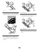


5.Installthenewdrivebelt,routingitasshownin
(Figure28).
Figure28
1.Brakespring(installon
idlerarmhere)
3.Enginepulley
2.Idlerpulley4.Rotorpulley
Note:Routethenewdrivebeltrstaroundthe
enginepulley,thentheidlerpulley,andnallyaround
thelooserotorpulleypositionedjustabovetherotor
shaft(Figure27).
6.Installtherotorpulleyontotherotorshaft
(Figure27).
7.Installthecurvedwasherandtherotorpulleybolt
andtightenthemsecurely(Figure27).
Note:Theconcavesideofthecurvedwashergoes
againsttheoutsideofthepulley.
8.Installthebrakespringontotheidlerarm(Figure28).
9.Installthedrivebeltcoverwiththeboltsyou
removedinstep1.
Note:Ensurethatthedrivebeltisproperlyadjusted
andoperating;refertoCheckingtheControlCable
andAdjustingtheControlCable.
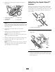
AdjustingtheQuickShoot™
Control
Ifthereismorethan1/2inch(13mm)ofslackinthe
QuickShootcablewhenyoupullonthelowercable
casing(Figure29)orthedischargechutedoesnotrotate
leftandrightinequalangles,adjusttheQuickShoot
controlcables.
Figure29
1.1/2inch(13mm)maximum
1.LoosenthetwoQuickShootcontrolcableclamps
(Figure30).
Figure30
1.Cableclamps
2.PositiontheQuickShootcontrolbetweenthetwo
arrowslocatedontherighthandsideoftheupper
handle(Figure31).
16