
Operator's Manual
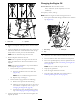
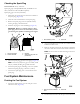
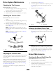
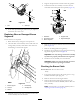
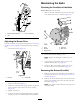
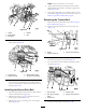
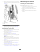
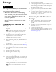


Figure33
1.Nut
2.Shearpin
4.Iftheshearpinisdamaged,removethepin,replaceit,
andsecuretheitwithanut.
ReplacingWornorDamagedBroom
Segments
ServiceInterval:Asrequired.
1.Raisethebroombysettingthecasterpositions.
2.Onbothsidesofthemachine,removeandretainthe
carriagebolts,washers,andlocknutsthatsecurethe
endbearingstothebroomsupport.
Figure34
1.Broomsupport4.Endbearing
2.Locknut
5.Carriagebolt
3.Washer
3.Manuallypullthepowerunitrearwardtoremovethe
broomassemblyfromthemachine.
4.Supportthesplineshaftoneithersideofthegearbox.
5.Standthebroomcoreassemblyonendsothatthe
removableendretainerplatefacesupward(Figure35).
Figure35
1.Hardware
4.Supportshaft
2.End-retainerplate
5.Alignmentngers
3.Broomsegment
6.Removeandretainthehardwarefromtheend-retainer
plate(Figure35).
7.Removethedamagedbroomsegment(s).
8.Installthenewsegment(s)bystaggeringthemetalring
alignmentngersasshowninFigure35.
Important:Youmaydamagethebroomassembly
ifyoudonotproperlyinstallthebroomsegments.
9.Installthebroomassemblyontothemachine.
Important:Makesurethatthebearingsetscrews
aretightenedbeforeoperatingthebroom.
CheckingtheBroomCable
ServiceInterval:Aftertherst2hours
Yearly
1.Turnofftheengine,waitforallmovingpartstostop,
anddisconnectthespark-plugwire.
2.Removethebeltcoverandengineshield.
3.Withthebroomleverdisengaged,ensurethegap
betweenthebroom-clutchassemblyandthetabis3.2
mm(1/8inch).
Note:Ifthebroomisnotproperlyadjusted,referto
AdjustingtheBroomDrive(page25).
24