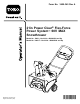
Form No. 3450-345 Rev A 21in Power Clear® Flex-Force Power System™ 60V MAX Snowthrower Model No. 39921—Serial No. 400000000 and Up Model No. 39921T—Serial No. 400000000 and Up Register at www.Toro.com.
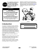
Whenever you need service, genuine Toro parts, or additional information, contact an Authorized Service Dealer or Toro Customer Service and have the model and serial numbers of your product ready. Figure 1 identifies the location of the model and serial numbers on the product. Write the numbers in the space provided. For assistance, please see www.Toro.com/support for instructional videos or contact 1-888-384-9939 before returning this product.
Safety-Alert Symbol Safety The safety-alert symbol (Figure 2) shown in this manual and on the machine identifies important safety messages that you must follow to prevent accidents. READ ALL INSTRUCTIONS WARNING—When using an electrical machine, basic safety precautions should always be followed to reduce the risk of fire, electric shock, or injury, including the following: g000502 I.
unpredictable behavior that results in fire, explosion, or risk of injury. 8. 9. If the supply cord to the battery charger is damaged, contact an Authorized Service Dealer to replace it. Charge the battery pack with only the battery charger specified by Toro. A charger suitable for 1 type of battery pack may create a risk of fire when used with another battery pack. 10. Charge the battery pack in a well-ventilated area only. 11.
• Do not disassemble the battery pack. 12. • Replace the battery pack with a genuine Toro battery pack only; using another type of battery pack may cause a fire or risk of injury. SAVE THESE INSTRUCTIONS • Keep battery packs out of the reach of children and in the original packaging until you are ready to use them. IV. Maintenance and Storage 1.
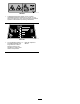
Safety and Instructional Decals Safety decals and instructions are easily visible to the operator and are located near any area of potential danger. Replace any decal that is damaged or missing. decal145-8252 decal145-8251 145-8252 145-8251 decal137-2257 137-2257 3. Thrown object hazard—keep bystanders away. 1. Warning—read the Operator’s Manual. 2.
decal137-9463 137-9463 1. The battery pack is charging. 2. The battery pack is fully charged. 3. The battery pack is over or under the appropriate temperature range. 4. Battery pack charging fault decal137-9462 137-9462 decal137-9461 137-9461 1. Battery charge status decal137-9454 137-9454 1. Read the Operator’s Manual. 2. Call2Recycle® battery recycling program decal94-8072 94-8072 7 3. Keep away from open fire or flames. 4. Do not expose to rain.
decal114-9035 114-9035 1. Cutting/dismemberment hazard of hand, impeller; cutting/dismemberment hazard of foot, auger—do not place your hand in the chute; remove the key and read the Operator’s Manual before performing maintenance. decal147-1787 147-1787 1. The combined Ah rating of 2. Read the Operator's Manual. all installed batteries must be greater than 4.0Ah to start the machine, and greater than 7.5Ah for best runtime and operation.
Setup Important: The battery pack is not fully charged when you purchase it. Before using the machine for the first time, refer to Charging the Battery Pack (page 14). 1 Mounting the Battery Charger (Optional) Parts needed for this procedure: Procedure If desired, mount the battery charger securely on a wall using the wall-mount key holes on the back of the charger. Mount it indoors (such as a garage or other dry place), near a power outlet, and out of the reach of children.
2 Unfolding the Handle Parts needed for this procedure: 2 Handle lock 2 Handle knob Procedure g389401 3 Installing the Discharge Chute Parts needed for this procedure: 1 Discharge chute assembly 3 Hex washer head screw 1 Chute handle Procedure g291515 10
Specifications Product Overview Battery Pack Model Battery pack capacity 88625 2.5 Ah 135 Wh Battery manufacturer rating = 60V maximum and 54V nominal. Actual voltage varies with load. Battery Charger Model 88602 Type 60V MAX Lithium-Ion Battery Charger Input 120V AC 50/60Hz Max 2.0A Output 60V MAX DC 2.0A Appropriate Temperature Ranges g381633 Figure 6 1. Discharge chute 6. Headlight 2. Chute deflector 3. Chute-deflector trigger 7. ECO switch 8. Electric-start button 4. Chute handle 5.
Starting the Machine Operation Installing the Battery Pack(s) Important: Use a battery pack only in temperatures that are within the appropriate range; refer to Specifications (page 11). 1. 2. 1. Ensure that the battery pack (or battery packs) are installed in the machine; refer to Installing the Battery Pack(s) (page 12). 2. Insert the electric-start button into the electric starter (A of Figure 9). 3. Squeeze the bail and hold it to the handle (B and C of Figure 9).
Removing the Battery Pack(s) from the Machine Activating ECO Mode Using ECO mode may extend battery life by reducing rotor speed; use ECO mode whenever you are moving snow a short distance. Activate ECO mode using the ECO switch as shown in Figure 6. 1. Lift up the battery-compartment lid. 2. Press the battery pack-latch to release the battery pack(s) and remove the battery pack(s). 3. Close the battery-compartment lid.
Charging the Battery Pack 4. To remove the battery pack, slide the battery backward out of the charger. Important: The battery pack is not fully charged when you purchase it. Before using the tool for the first time, place the battery pack in the charger and charge it until the LED display indicates the battery pack is fully charged. Read all safety precautions. 5. Refer to the following table to interpret the LED indicator light on the battery charger.
Adjusting the Discharge Chute and Chute Deflector Clearing a Clogged Discharge Chute To adjust the discharge chute, move the chute handle. If the machine is running but there is no snow coming out of the discharge chute, the discharge chute may be clogged. To adjust the chute deflector (and therefore the height of the snow stream), squeeze the trigger and raise or lower the chute deflector (Figure 13).
Maintenance Stop the machine, remove the electric-start button, remove the battery pack from the machine, and wait for all movement to stop before adjusting, servicing, cleaning, or storing the machine. Inspecting the Rotor Blades Service Interval: Yearly—Inspect the rotor blades and have an Authorized Service Dealer replace the rotor blades and scraper if necessary. Before each session, inspect the rotor blades for wear.
Storage Important: Store the machine, battery pack, and charger only in temperatures that are within the appropriate range; refer to Specifications (page 11). Important: If you are storing the battery pack for the off-season, charge it until 2 or 3 LED indicators turn green on the battery. Do not store a fully charged or fully depleted battery.
Troubleshooting Perform only the steps described in these instructions. All further inspection, maintenance, and repair work must be performed by an authorized service center or a similarly qualified specialist if you cannot solve the problem yourself. Problem The machine does not run or does not run continuously. Possible Cause 1. The battery pack is low on charge. 1. Charge the battery pack. 2. The battery is not fully installed in the machine. 2.
Problem The LED indicator light on the battery charger is blinking red. The machine is producing a beeping sound. Possible Cause Corrective Action 1. There is an error in the communication between the battery pack and the charger. 1. Remove the battery pack from the battery charger, unplug the battery charger from the outlet, and wait 10 seconds. Plug the battery charger into the outlet again and place the battery pack on the battery charger.
California Proposition 65 Warning Information What is this warning? You may see a product for sale that has a warning label like the following: WARNING: Cancer and Reproductive Harm—www.p65Warnings.ca.gov. What is Prop 65? Prop 65 applies to any company operating in California, selling products in California, or manufacturing products that may be sold in or brought into California.