FORM NO. 85-9350 SET-UP AND PARTS MODEL NO. 40025-80001 & UP CATALOG RESPIRATOR KIT _ for the Multi Pro 1100, 5500 and Workman Vehicles To assure maximum safety, optimum performance, and to gain knowledge of the product, it is essential that you or any other operator of this Vehicle read and understand the contents of this manual before the engine is ever started. Pay particular attention 1o the SAFETY. INSTRUCTIONS highlighted by the triangular safety alert symbol. A\ SAFETY INSTRUCTIONS Keep this Operator
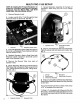
MULTI PRO 1100 SET-UP NOTE: If installing the Personal Respirator on a Multi Pro 1100 with a Hose Reel or a Operator Enclosure. See the “MULTI PRO 1100 WITH HOSE REEL OR ENCLOSURE SETUP', 1. Remove Operator’s seat. 2. Locate, mark & drills 1” hole through the Seat Panel and insert {1) Grommet. See FIG. 1. FIG. 1 1. Grommet 2. Respirator Power Gable 3. Push the Respirator Power Cable through the Grommet, Lay Respirator Power Cable across Seat Panel as shown in FIG. 1. 4.
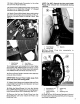
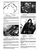
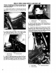
12. Attach Male/Female Connector to the other end of In-line Fuse Assembly. 13. Route Power Cable following Main Vehicle Wire Harness out of Seat Box through “U” shaped bracket and into Steering Console. 14. Attach Ground Wire (black) along with Ignition Ground to the bolt securing the bottom of the L.H. Steering Console Panel to Vehicle Frame. See FIG. 5. Fig§ 1. Male/Female 2, Hour Meter Connector 3.
MULTI PRO 1100 WITH ENCLOSURE SET-UP NOTE: If installing the Personal Respirator on a Multi Pro 1100 without a Operator Enclosure. See the “MULTI PRO 1100 SETUP” or the “MULTI PRO 1100 WITH HOSE REEL SETUP". NOTE: ¥f installing the Personal Respirator on a Multi Pro 1100 with a Operator Enclosure and a Hose Reel, install the Operator Enclosure and Hose Reel per instructions included with those kits. Install the Respirator Angle in FIG. 1 in same location on top of bracket on the Hose Reel Mounting Assembly.
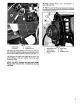
FiG. 4 1. Male/Female 2. Hour Meter Connector 3. ignition Ground 14. Slide the Motor/Blower Unit into the Vehicle Mount PAP Assembly and secure using Spring on top of Vehicle Mount PAP Assembly. See FIG. 5. 15. Remove the Inlet and Outlet Plugs from the Motor/Blower Unit and install the Filter and Breathing Tube. NOTE: Do NOT discard the Inlet and Outlet Plugs they should be reinstalled during cleaning. 16.Plug Power Plug into receptacle in Motor/Blower Unit.
MULTI PRO 1100 WITH HOSE REEL SETUP NOTE: If installing the Personal Respirator on a Multi Pro 1100 without a Hose Reel. See the “MULTI PRO 1100 SETUP", 1. Installment Hose Reel Kit as per the instructions included with that kit, 2. Locate, mark and drill (2) 11/32" diameter holes through both walls of the tube on the L.H. side of the Hose Reel Mounting Assembly. See FIG. 1. DRILL TWO 11/32" HOLES: 1. Hose Reel Mounting Assembly 3.
11, Attach Male/Female Connector to the other end of In-line Fuse Assembly. IMPORTANT: Secure Power Cable away from belts and other and moving pairs. 12, Attach Ground Wire (black) along with Ignition Ground to the bolt securing the bottom of the LH. Steering Console Panel to Vehicle Frame. See FIG. 5. Fig 1. Femaleness 2. Hour Meter Connector 3. Ignition Ground 13. Unplug power wire (green) from Hour Meter and replace with Male/Female Connector on the Hot Wire (red).
MULTI PRO 5500 SET-UP NOTE: if installing the Personal Respirator on a Multi Pro 5500 with a Cab. See the “MULTI PRO 5500 WITH CAB SETUP”, 1. Remove Operator's seat. 2. Ovate, mark & drill a 1” hole through the Seat Panel and insert (1) Grommet. See FIG. FIG. 1 1. Grommet 2. Respirator Power Cable 3. Push the Respirator Power Cable through the Grommet. Lay Respirator Power Cable across Seat Panel as shown in FIG. 1. 4.
10, Cut the In-line Fuse wire in center of wire. Strip 1/4” of insulation farm each end, (73 Fig 1. Conduit 4. 2. Spade Terminal 5. 3. Inline Fuse Assembly 11. Strip 1/4” of insulation off of the end of the Hot Wire (red) in the Power Cable and attach to end of the In-line Fuse Assembly with the black cap using Butt Splice. Butt Splice Ring Terminal 12. Attach Ring Terminal to the other end of in-line Fuse Assembly, 13.
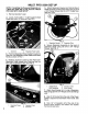
MULTI PRO 5500 WITH CAB SET-UP NOTE: If installing the Personal Respirator on a Multi Pro 5500 without a Cab. See the “MULTI PRO 5500 SETUP". 1. Locate, mark & drill a 17 hole through back of thg Enter Console and insert (1) Grommet. See FIG. 1. Fig 1. Backing Angle 3. Vehicle Mount 2. Power Cable PAP Assembly 4. Secure Vehicle Mount PAP Assembly to Backing Angles using (3) 5/16 x 3/4” flange screws and flange nuts. See FIG. 3. 5.
6. Strip §” of Conduit from the end of the Power Cable to expose red and black wires inside. See FIG. 5. 1% FIG. 5 1. Conduit 4, 2. Spade Terminal 5, 3. inline Fuse Assembly 7. Strip 1/4” of insulation off of the end of the Ground Wire (black) and attach the Spade Terminal to bare wire. Butt Splice Ring Terminal 8. Cut the In-line Fuse wire in center of wire. Strip a 1/4” of insulation from each end. 9.
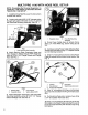
WORKMAN SET-UP NOTE: If installing the Personal Respirator on a Workman with a Cab. See the “WORKMAN WITH CAB SETUP". 1. Attach Vehicle Mount PAP Assembly to Respirator Plate using (2) 5/16 x 3/4" Flange Screws and (4) 5/16" Flange Nuts. See FIG. 1. FIG. 1 1. Respirator Plate 3. Vehicle Mount 2. R Clamp PAP Assembly 2. Secure Respirator Assembly to the center of Setback Support using (3} 5/16 x 3/4” flange screws, flange nuts and R-Clamps. 3.
12, Attach Hood Hanger using (2) R-Clamps, 5/16 x 3/4” flange bolts and flange nuts. See FIG. 4, FiG. 4 1. Hood Hanger 4. Spring 2. R-Clamps 5. Power Plug 3. Motorbike Unit 6. Filter 7. Breathing Tube 13. Slide the Motor/Blower Unit into the Vehicle Mount PAP Assembly and secure using Spring on top of Vehicle Mount PAP Assembly. See FIG. 4. 14. Remove the Inlet and Outlet Plugs from the Motor/Blower Unit and install the Filter and Breathing Tube.
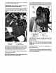
WORKMAN WITH CAB SET-UP NOTE: I installing the Personal Respirator on a Workman without a Cab. See the “WORKMAN SETUP”, 1. Locate, mark and drill (4) 5/16" diameter holes in the rear Cab Panel. See FIG. 1 {dimensions are from top and L.H. side bends in rear Cab Panel. FIG. 3 1. Power Cable 4. Route Power Cable down back of Seat Box. Route following Brake line to front of vehicle and up through floorboard. See FIG. 4, FIG. 1 2.
5. Strip 8" of Conduit from the end of the Power Cable to expose red and black wires inside. See FIG. 5. FIG. 6 1. Conduit 4. Butt Splice 2. Ring Terminal 5. Female Connector 3. In-line Fuse Assembly 8. Strip 1/4" of insulation off of the end of the Ground Wire {black) and attach the Ring Terminal to bare wire. 7. Cut the In-line Fuse wire in center of wire. Strip 1/4” ot insulation from each end. 8.
*, Additional parts used in Workman, Workman with Cab, Multi Pro 1100 with Hose Reel, Multi Pro .19 1100 with Enclosure & 5500 with Cab Set-ups. > 1ao8 NOTE: Parts shown are in Multi Pro 1100 & 5500 setup configuration, Electrical Connectors (See Setup) # [Part No. Description Qty # 1 Part No.
OPTIONAL BELT MOUNT ACCESSORIES # |Part No, Description ity # 1 Part No.
The Toto Commercial Products Two Year Limited Warranty The Toto Company warrants your 1996 or newer Taro Commercial Product (*Product”) purchased after January 1, 1997, 1o be free from defects In materials or workmanship for the period of time listed below. Where a warrant able condition exists, Toto will repeal the Product at no cost to you including diagnosis, labor , parts, and transportation. This warranty begins on the date the Product is delivered to the original retail purchaser.