
Lawn Mower User Manual


Groundsmaster 4100--DHydraulic System Page 4 -- 116
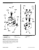
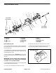
Assembly (Fig. 80)
NOTE: When assemblingthe motor, checkthe identifi-
cation marks made during disassembly to make sure
the parts are properly aligned during assembly.
1. LubricateO--rings,pressureseals,back--upgaskets
and seal grooves with a thin coat of petroleum jelly. Lu-
bricateallotherinternalparts freelywithcleanhydraulic
oil.
2. Install new shaft seal into front flange.
3. Install lubricated pressure seals into the grooves in
thefront flangeand rearcover. Followby carefullyplac-
ing the back--up rings into the grooves.
4. Install new O--rings to the body.
5. Lubricate gear faces and bearing surfaces of drive
gear, idler gear andbearing blocks with clean hydraulic
oil.Carefullyassemblebearing blocksandgearsnoting
identification marks made during disassembly.
6. Position the motor body on its side. Carefully slide
bearing block and gear assembly into the body cavity
using identification marks made during disassembly.
7. Remove any excess lubrication from mating sur-
faces of body, rear cover and front flange. Make sure
that these surfaces are clean and dry.
8. Install dowel pins in body.
IMPORTANT: Do not dislodge O--rings, pressure
seals or back--up rings during final assembly.
9. Gently slide the rear cover onto the assembly using
marker or scribe mark for proper location. Firm hand
pressure should besufficient toengage the dowel pins.
10.Positionthemotorwithrearcoverdownwards.C are-
fullyslidethefrontflangeontotheassemblyusingmark-
er line for proper location.
11.Install the four (4) cap screws and hand tighten.
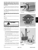
IMPORTANT: Prevent damage when clamping the
deck motor into a vise; clamp on the front flange
only. Also, use a vise with soft jaws.
12.Place motor front flange in a vise and alternately
torque the screws from 33 to 40 ft--lb (45 to 55 N--m).
13.Put a small amount of hydraulic oil in port on motor
and rotate driveshaft one revolution. Protect the shaft if
using a pliers. If drive shaft binds, disassemble motor
and repeat assembly process.
14.Make sure that tapered surface of motor shaft and
spider hub are thoroughly clean.
15.Place woodruff key in motor shaft slot. Install spider
hubandtabwasheronshaft.Securespiderhubtoshaft
withnut. Torquenut from27 to 33 ft--lb (37to 45N--m).
16.Securenuttomotorshaftbybendingsmalltaboftab
washer into keyway and large tab against nut.
17.Remove motor from vise.