
Lawn Mower User Manual


Groundsmaster 4100--D Hydraulic SystemPage 4 -- 119
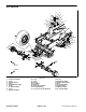
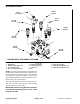
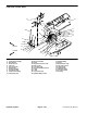
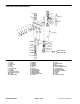
Removal (Fig. 85)
NOTE: The ports on the manifold are marked for easy
identification ofcomponents.Example: SV1 is the deck
solenoid valve and P1 is a gear pump connection port.
(SeeHydraulicSchematicin Chapter9 -- FoldoutDraw-
ingstoidentifythefunctionofthehydrauliclinesandcar-
tridge valves at each port).
The controlmanifolds for thethree (3)cutting deck sec-
tions are very similar.
IMPORTANT: Whenservicingthedeckcontrolman-
ifolds, DO NOT interchange parts from one control
manifold to another.
1. Read the General Precautions for Removing and
Installing Hydraulic System Components at the begin-
ning of this section.
2. Topreventcontaminationofhydraulicsystemduring
manifold removal,thoroughly clean exterior of manifold
and fittings.
3. Disconnect electrical connector from the solenoid
valve.
4. Disconnect hydraulic lines from manifold and put
capsor plugson openhydraulic linesand fittings.Label
disconnected hydraulic lines for proper installation.
5. Remove hydraulic manifold from the frame using
Figure 85 as guide.
6. If hydraulic fittingsare to beremoved from manifold,
mark fitting orientation to allow correct assembly. R e-
move fittings from manifold and discard O--rings.
Installation (Fig. 85)
1. If fittings wereremoved from manifold,lubricate and
place newO--rings onto fittings.Install fittings intoman-
ifold openings using marks made during the removal
process to properly orientate fittings. Tighten fittings
(see Hydraulic Fitting Installation in the General Infor-
mation section of this chapter).
2. Install hydraulic manifold to the frame using Figure
85 as guide.
3. Remove caps and plugs from fittings and hoses.
Properly connect hydraulic lines to manifold.
4. Connect electrical connector to the solenoid valve.
Hydraulic
System