
Lawn Mower User Manual

Groundsmaster 4100--DPage 5 -- 14Electrical System
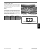
PTO Switch
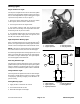
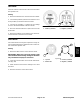
ThePTOswitchisusedtoengageordisengagethecut-
tingdeck.ThePTOswitchisattachedtothecontrolcon-
sole next to the operator seat (Fig. 17).
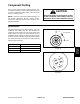
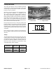
TheswitchterminalsaremarkedasshowninFigure18.
Thecircuitry ofthe PTOswitch isshown inthe chartbe-
low. With the use of a multimeter (ohms setting), the
switch functions may be tested to determine whether
continuityexistsbetween thevariousterminalsforeach
position. Verify continuity between switch terminals.
NOTE: The PTO ENGAGEpositionrequires liftingand
pushing the lever toward the switch keyway. The PTO
OFF position occurs whenthe lever is pushed opposite
the keyway.
SWITCH
POSITION
NORMAL
CIRCUITS
OTHER
CIRCUITS
PTO ENGAGE 1+2 4+5
CENTER (ON) 1+2 NONE
PTO OFF NONE NONE
1. PTO switch 2. Control console
Figure 17
1
2
Figure 18
12
45
BACK OF PTO SWITCH
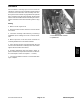
Alarm Silence and Temperature Override Switches
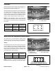
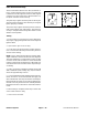
The alarm silence and temperature override rocker
switches are located on the control console next to the
operator seat (Fig. 19). These switches are identical.
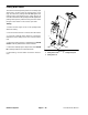
Testing
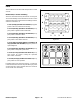
TheswitchterminalsareshowninFigure20.Thecircuit-
ry of the switches is shown in the chart below. With the
use ofa multimeter (ohms setting), the switchfunctions
may be tested to determine whether continuity exists
between the various terminals for each position. Verify
continuity between switch terminals.
SWITCH
POSITION
NORMAL
CIRCUITS
OTHER
CIRCUITS
ON 2+3 5+6
OFF 1+2 4+5
NOTE: Terminals 7 (--) and 8 (+) on alarm silence and
temperature override switches are for the switch light.
1. Control console
2. Alarm silence switch
3. Temp. override switch
Figure 19
1
2
3
Figure 20
BACK OF ALARM SILENCE AND
132
45 6
8
7
TEMPERATURE OVERRIDE SWITCHES