
Lawn Mower User Manual

Groundsmaster 4100--DPage 5 -- 20Electrical System
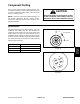
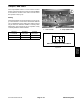
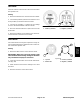
Glow and Power Relays
The Groundsmaster 4100--D uses two (2) identical re-
lays to control electrical power circuits. The glow relay
is attached to the the right side of the fuel tank support
under thehood. The powerrelay is attachedto thecon-
trol panel under the console housing.
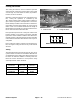
The glow relay supplies electrical power for the engine
glowplugswhenenergized.Thestartrelayisenergized
by the glow plug controller.
The power relay supplies electrical power for fuses F9
(TEC--5002 outputs),F10, F11and F12.Themainpow-
er relay is energized when the ignition switch is in the
START or RUN position.
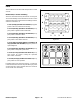
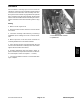
Testing
1. Park machineon alevels urface, lowercutting deck,
stop engine, apply parking brake and remove key from
ignition switch.
2. Open hood to gain access to relay.
3. Locate relay and disconnect the machine wire har-
ness connector from the relay. Remove relay from ma-
chine for easier testing.
NOTE: Prior to taking small resistance readings with a
digital multimeter, short the meter test leads together.
The meter will display a small resistance value (usually
0.5 ohms or less). This resistance is due to the internal
resistanceofthe meterandtestleads.Subtractthisval-
uefrom fromthemeasured valueofthecomponent you
are testing.
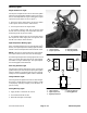
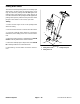
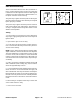
4. Verify coil resistance between terminals 85 and 86
with a multimeter (ohms setting) (Fig. 29). Resistance
should be approximately 72 ohms.
5. Connectmultimeter(ohmss etting)leadstorelayter-
minals 30 and 87. Ground terminal 86 and apply +12
VDCtoterminal85.Therelayshouldhavecontinuitybe-
tweenterminals30and87as +12VDCisapplied toter-
minal 85.The relay should nothave continuity between
terminals30and 87as+12VDCis removedfromtermi-
nal 85.
6. After testing is complete, install relay to frame and
connect wire harness to relay.
7. Close and secure hood.
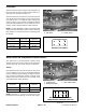
Figure 29
86 87
85 30
85 86
87
30