
Lawn Mower User Manual


Groundsmaster 4100--D Page 6 -- 25 Axles, Planetaries and Brakes
7. Secure the lock nut with the stake washer.
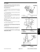
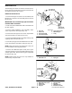
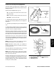
8. Useadepthgaugetomeasurethedistancefromthe
endfaceoftheinput shaft/piniongear tothematingsur-
face of the bearing case. Subtract the “Design Cone
Center Distance” from this distance to determine initial
shim thickness (Fig. 32).
DESIGN CONE CENTER DISTANCE (distance
from mating surface of axle s upport to end face of
pinion gear):
1.870 +
0.002 in. (47.5 + 0.05 mm)
NOTE: Bearing case shims are available in 0.004 in.
(0.1 mm) and 0.008 in. (0.2 mm) thickness.
9. CoatnewO-ringswithgreaseandinstallthebearing
caseinthegearcase.Placeshimsonthegearcaseand
temporarily install gear case assembly into axle case.
Tighten mounting nuts and screws from 35 to 41 ft-lb
(47to56N--m).
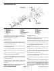
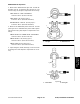
10.Insert a screwdriver through the drain plug hole to
hold ring gear andmeasurethe pinion gear to ring gear
backlash (Fig. 33).
PINION GEAR TO RING GEAR BACKLASH:
0.004 to 0.016 in. (0.10 to 0.40 mm)
11.Adjustbacklashbyincreasingorreducinggearcase
shim thickness.
12.Checkpiniongeartoringgearengagement(seePin-
ionGeartoRingGearEngagementinthissectionofthis
manual).
13.Place the correct combination of shims on the gear
case. Tighten mounting nuts and screws from 35 to 41
ft-lb (47 to 56 N--m).
14.Install retaining rings and drivengear on input shaft/
pinion gear.
15.Ifthe drivegear(ondrive motorshaft)wasremoved,
install the retaining rings and drive gear on the motor
shaft.
16.Use a new gasket and install the cover plate.
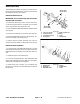
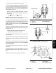
1. Oil seal
2. Bearing case
3. Seal garter spring
Figure 31
0.040 in. (1.0 mm)
1
2
3
1. Input shaft/pinion gear 2. Bearing case
Figure 32
1
2
Design
Cone Center
Distance
1. Axle case
2. Screwdriver
3. Dial indicator
4. Input shaft/pinion gear
Figure 33
1
2
3
4
Axles, Planetaries
and Brakes