
Lawn Mower User Manual

Groundsmaster 4100--DPage 3 -- 14Kubota Diesel Engine
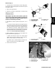
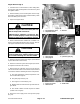
9. Disconnect throttle cable from the speed control le-
ver by removing the flat washer and lock nut (Fig. 14).
Loosenjam nut andseparate cablefrom cable support.
Position cable away from engine.
10.Remove fasteners that secure the upper radiator
shroud to the lower shroud and radiator (see Radiator
Removal inthis section). Positioncoolant reservoir and
bracket away from the radiator. Remove upper radiator
shroud from machine.
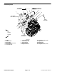
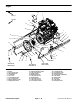
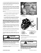
11.Remove fan hub and fan from hydraulic fan motor
(Fig. 15).
A. Removehexnut(item9)andwasher(item8)that
secure fan hub and fan assembly to fan motor.
NOTE: The fan motor shaft is tapered.
B. Usesuitablepullertoremovefanhub(withfanat-
tached) fromfan motor shafttaking care tonot dam-
age fan. Remove fan hub and fan from machine.
IMPORTANT: The hydraulicpumpassembly can re-
main in machine during engine removal. To prevent
pump from shifting or falling, make sure to support
pump assembly before mounting fasteners are re-
moved.
12.Support hydraulic pump assembly. Remove fasten-
ers that secure pump assembly to engine (see Pump
Assembly Removal in the Service and Repairs section
of Chapter 4 -- H ydraulic System).
13.Makesureall cableties securingthewiringharness,
fuellines orhydraulic hosesto theengine areremoved.
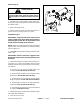
14.Connect hoist or lift to the lift tabs on engine.
15.Remove flange nuts, rebound washers and cap
screws securing the engine mounts to the engine sup-
ports.
CAUTION
One person should operate lift or hoist while
another person guides the engine out of the ma-
chine.
IMPORTANT: Make sure not to damage the engine,
fuel and hydraulic lines, electrical harness or other
components while removing the engine.
16.Slowly remove engine assembly from the machine.
17.Ifnecessary,removeenginemountsfromtheengine
using Figure 9 as a guide.
Figure 13
1. Fuel pump
2. Fuel supply hose
3. Throttle cable
3
1
2
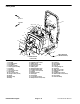
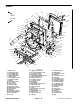
Figure 14
1. Lock nut
2. Flat washer
3. Throttle lever
4. Lock nut
5. Flange head screw
6. Cap screw
7. Flange head screw
8. Spring washer (2 used)
9. Ball joint
10. Cap screw (2 used)
11. Throttle cable
12. Cable support
2
3
4
8
9
6
7
1
5
10
11
12
Engine Installation (Fig. 9)
1. Ifremoved,installenginemountstotheengineusing
Figure 9 as a guide.
2. Connect hoist or lift to the engine lift tabs.
CAUTION
One person should operate lift or hoist while
another person guides the engine into the ma-
chine.
IMPORTANT: Make sure not to damage the engine,
fuel and hydraulic lines, electrical harness or other
parts while installing the engine.