
Lawn Mower User Manual

Groundsmaster 4100--D Hydraulic SystemPage 4 -- 55
Procedure for Steering and Lift/Lower Gear Pump
Flow Test
Output from the steering and lift/lower gear pump sec-
tionis equally dividedby a proportionalvalve toprovide
flowtothesteeringcircuitand theliftcircuit.Totestgear
pump flow, testing ofboth steeringand lift/lower circuits
is required. Total gear pump flow is the combined flow
from the two circuits.
1. Make sure hydraulic oil is at normal operating tem-
peraturebyoperatingthemachineforapproximately10
minutes. Make sure the hydraulic tank is full.
2. Parkmachineonalevelsurfacewiththecuttingdeck
loweredandoff.Makesureengineisoffandtheparking
brake is engaged. Raise seat.
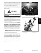
CAUTION
Prevent personal injuryand/or damageto equip-
ment. Read all WARNINGS, CAUTIONS and Pre-
cautions for Hydraulic Testing at the beginning
of this section.
IMPORTANT: Make sure that the oil flow indicator
arrow on the flow gauge is showing that the oil will
flow from the pump section, through the tester and
into the hydraulic hose.
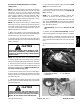
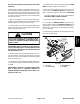
3. Withtheengineoffandcuttingdecklowered,discon-
nect the hydraulic hose from the 90
o
fitting in the third
gear pump section which supplies the steering and lift/
lower circuits (Fig. 43).
4. Installtesterin seriesbetweenthefittingandthedis-
connectedhose.Makesurethetesterflowcontrolvalve
is OPEN.
IMPORTANT: The pump is a positive displacement
type. If pump flow is completely restricted or
stopped, damage to the pump, tester or other com-
ponents could occur.
5. Starttheengineandmovethrottletofullspeed(2870
RPM). DO NOT engage the cutting deck.
6. While watching pressure gauges, slowly close flow
control valve until 1000 PSI (69 bar) is obtained on
gauge. Verify enginespeed continues tobe 2870 RPM.
GAUGE READING TO BE: Flow approximately 7
GPM (26.3 LPM) at 1000 PSI (69 bar).
7. Stop engine and record test results.
8. If a pressure of 1000 PSI (69 bar) could not be ob-
tained or flow is lower than 6GPM(22.3LPM)(85% of
expectedflow),check forrestrictioninpump intakeline.
Ifintakeline isnotrestricted,consider thatgearpump is
worn or damaged.
9. When testing is complete,removetester and recon-
nect hose to pump fitting.
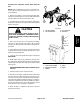
1. Gear pump
2. Fan drive manifold
3. Steering/lift hose
4. 90
o
fitting
Figure 43
1
2
3
4
Hydraulic
System