
Installation Instructions

1
2
3
4
5
6
7
8
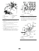
G016800
Figure3
1.Fork5.90degreehosebarb
2.Straighthosebarb
6.Hoseclamp
3.Tee7.Adaptor
4.Connector
8.Hose
2.Secureeachhosebarbtotheteeusingafork
(Figure3).
3.Jointheteetotheadaptorwithaconnectorand
securethemwith2forks(Figure3)..
4.Threadtheadaptorintothetopofthetank
(
Figure3).
5.Attachoneendofthehoseprovidedwiththekitto
the90degreehosebarb(Figure3).
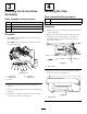
6.For41008:Replacetheexistingvalvewiththe
providedhosebarb(
Figure4),thenattachthehose
tothehosebarbandsecureitwithahoseclamp.
g016968
1
2
Figure4
1.Hosebarb2.Hoseclamp
7.For41009:Installtheagitationvalveassemblyin
theindicatedlocationusingtheboltsalreadyonthe
sprayer(Figure5),thenattachthekithose,agitation
hose,andsupplyhosetotheassemblyandsecureit
withahoseclamp.
g016998
1
2
3
4
5
Figure5
1.Agitationvalveassembly4.Agitationhose
2.Kithose
5.Supplyhose
3.Hoseclamp
3