
Installation Instructions

3
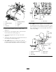
InstallingtheIn-LineHose
Assembly
Partsneededforthisprocedure:
2Hoseclamp
2
Straighttting
2
O-ring
1Ballvalve
Procedure
1.For41008:Cuttheagitationhose18inchesfrom
thebarb(
Figure6).
For41009:Cuttheagitationhose10inchesfrom
thebarb(Figure6).
1
1
2
2
3
34
5
G016801
Figure6
41008shown
1.Hoseclamp4.Ballvalve
2.Straighttting
5.Agitationhose
3.O-ring
2.PlaceanO-ringintoeachsideoftheballvalve
(Figure6).
3.Attachastraightttingtoeitherendoftheballvalve
(Figure6).
4.Connecttheassemblytothehoseandsecurewith
hoseclampsoneachend(Figure6).
4
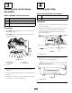
InstallingtheChip
Partsneededforthisprocedure:
1
Chip
1Decal
Procedure
1.Removethescrewssecuringtheconsolepaneland
removethepanel.
2.Removethecurrentchipandinsertthenewchip
usingthetoolprovided.Refertoinstructions
providedwiththeremovaltoolfortheproper
procedure(
Figure7).
g017130
1
Figure7
1.Chiplocation
3.Replacetheconsolecoverandinstallthedecalon
therearoftheconsole(Figure8).
g016999
1
Figure8
1.Decallocation
4