
Operator's Manual


All Rights Reserved
Printed in the USA
1
2003 by The Toro Company
8111 Lyndale Avenue South
Bloomington, MN 55420-1196
Boom Kit
for Multi-Pro
1200, 1250 and 5600 Sprayers
Model No. 41027
Form No. 3329-365 Rev A
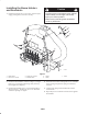
Installation Instructions
Installation
Note: Determine the left and right sides of the machine from the normal operating position.
Note: The figures used to illustrate these installation instructions are of the 5600 model sprayer. The appearance of your
sprayer may vary; however, the installation procedures remain the same.
Note: Depending on your model, you may have extra parts.
Description
Qty. Use
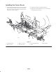
Boom holder
Bolt, 1/2 x 1-1/4 inch
Flange nut, 1/2 inch
Boom restraint hook
Boom holder sleeve
Spring
Knob
2
4
4
2
2
2
2
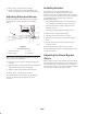
Installing boom holders and restraints
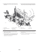
Center boom frame
Frame mounting bracket
Bolt, 1/2 x 3 inch
Bolt, 1/2 x 1-1/4 inch
Lock nut, 1/2 inch
Spacer, short
Spacer, long
Boom mounting bracket
U-bolt
Flange nut, 5/16 inch
Bolt, 3/8 x 1 inch
Washer, 1 inch
Flange nut, 3/8 inch
Boom clamp
Hose clamp
1
2
2
2
4
2
2
2
2
4
2
2
2
2
1
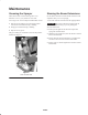
Installing the center boom
Boom extension
Bolt, 1/4 x 1-3/4 inch
Washer, 5/8 inch
Flange nut, 1/4 inch
Bolt, 5/16 x 1–1/2 inch
Flange nut, 5/16 inch
Hose clamp
2
8
8
8
2
2
2
Installing extension booms