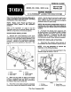
MODEL NO. 41036 30101 & Up FORM NO. 92-0383 SET-UP AND PARTS LIST TOR, oo Refer to the Sonic Boom Operators Manual for safety precautions and the proper operating instructions of the Sonic Boom. NOTE: "Left", ‘Rear" are referenced while seated In the operator’s position. Refer to the illustration on page 8 and the illustrated parts list to become familiar with the different components of the Sonar System. SONAR HEADS INSTALLATION: 1.
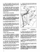
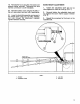
3. Mark the opposite ends of each of the actuator wire assembly as “Right* or "Left" to avoid confusion when the final connections are made at the sonar control box. 4. Route the sonar cables and the actuator wire assemblies along the top and toward the center of the boom frame. Use tie straps to secure both the sonar cables and the actuator wire assemblies at several points along the top of the boom frame and to the cross support as shown in FIG. 2. BOOM WITHOUT-ACTUATORS: 1.
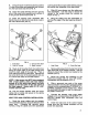
9. Crimp the push-on terminal onto the positive wire of the power wire assembly and connect it to the fuse block lead wire (FIG. 4). 10. Crimp the spade terminal onto the ground wire of the power wire assembly and connect it to the ground terminal block (FIG. 4). 11. Insert the 3-amp fuse (famished with Electric Boom Lift Kif) into the fuse block, next to the main vehicle fuse (FIG. 4). up through the floor board at the steering column and caress the underside of the dash panel. 2.
IMPORTANT: Note the tag on the power wire assembly. Damage to the electrical components will result if you do not observe the polarity as directed when connecting the power wire assembly. 9. Crimp the push-on terminal onto the positive wire of the power wire assembly and connect it to the fuse block lead wire (FIG. 4). 10. Crimp the spade terminal onto the ground wire of the power wire assembly and connect it o the ground terminal block (FIG. 4). 11, Insert 30-amp.
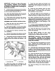
19. Reinstall the hood using the (15) screws and washers earlier removed. "Reconnect the wire harness connectors to both headlights, 20. Reinstall radiator cover using the hex hd. cap screws {and two nuts if applicability. 21. Lower the tank/skid assembly and secure to the vehicle frame using (2) 1/2° bolts, washers, and nuts through the attachment brackets. Tighten fasteners securely. BOOM HEIGHT ADJUSTMENT: 1. Tighten the adjustable clevis jam nut as close against the clevis as it will go (FIG. 7). 2.
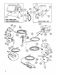
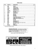
SONIC BOOM REF PART NOQ. DESCRIPTION Qry 1 42800 42811 Grommet . 3 4279 Central Box Bracket o1 4 24-5-AD Flat washer, 1/4 SAE. . .8 s 23.9.GD Lock Washer, 1/4 Med. 4 s 20-2A0 HHS, 174NCx 42797 Control Bax Bracket Says. L1 8 42792 Brace Strap ot s 20-24-GAD HHS. 5716 NCx 21-60-AGED Mach Crow, 42801 Etch Holder . 1 12 23.5.GD Lock Washer #6 4 13 227.A10 Hex Nut, 42812 Sonar Control Head 1 18 42810 Back Panel 1 18 42804 Toner Cover 42807 Special Se row .
“LSONAR™ N L Ho Tor POUR "R MOTOR & i “R SONAR" ~L.H. SONAR | ASSEMBLY SONAR CABLE SONAR CONTROL HEAD ACTUATOR WIRE ASSEMBLY SONAR CABLE L.H. ACTUATOR R.H. SONAR ASSEMBLY ACTUATOR WIRE ASSEMBLY MOPER WIRE ASSEMBLY R.H.