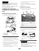
Form No. 3365-343 Rev A ProControl Spray System Multi-Pro® 5600 and 5700-D Turf Sprayer Model No. 41086—Serial No. 310000001 and Up To register your product or download an Operator's Manual or Parts Catalog at no charge, go to www.Toro.com.
This attachment controls the spray functions of a turf sprayer based on calculation from user input and is intended to be used by professional, hired operators in commercial applications. It is primarily designed for spraying golf course applications, parks, sports fields, and on commercial grounds. It is designed to only be used in conjunction with machines designated by the manufacturer. Figure 2 1. Safety alert symbol. This manual uses two other words to highlight information.
Safety Read and understand the contents of this manual before operating the console computer. • Keep this document with the Operator’s Manual for the Multi Pro® 5600 or 5700-D Turf Sprayer. • It is very important that all who operate this equipment have ready access to these instructions at all times. • Read these instructions and the instructions in the Operator’s Manual for the Multi Pro® 5600 or 5700-D Turf Sprayer carefully. Be familiar with the controls and the proper use of the equipment.
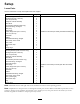
Setup Loose Parts Use the chart below to verify that all parts have been shipped.
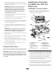
7. Secure the cables to the console computer by rotating the locking rings. CAUTION Many chemicals are hazardous and can cause personal injury or environmental damage if you apply them improperly. 8. Attach the console computer to the mounting bracket and secure it with the 2 mounting knobs (Figure 3). Ensure that sprayer hose connections are secure before operating the spray system. Mounting the Flowmeter 1. Disconnect the boom supply hose fitting from the boom valve assembly (Figure 4).
Installing the ProControl For Model Year 2010 and Newer only. 4. Install a barbed fitting into the end of the longer supply hose section and secure it with a hose clamp next to the fitting body. Important: Apply liquid soap to the barbed fitting to lubricate it. You must install the hose all the way onto the barb. Do not use petroleum-based lubricants such as grease or oil because they can damage the hose and contaminate the system. Installing the Console Computer 1.
6. Plug the cables into their corresponding inputs on the rear of the console computer and secure the cables by rotating the locking rings. 3. Locate the 90 degree fitting and long hose in loose parts. Lightly lubricate the barb with a non-petroleum based lubricant, such as vegetable oil. Install barbed fitting into the end of the 49 inch long supply hose from loose parts. Slide the hose clamp next to the fitting body and tighten to secure the hose to the fitting. 7.
1 13. Secure the shorter hose to the manifold and flowmeter respectively by sliding the hose clamps into positions over the barb and tightening. 14. Secure the flowmeter assembly to the flowmeter bracket with hose clamps. 15. Locate the spray system wiring harness routed to the boom valve manifold. Locate the capped round connector labeled flowmeter. 16. Remove the cap to expose the three-pin plug and connect it to the wire coming from the flowmeter. Secure the locking rings any locking rings if available.
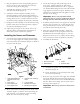
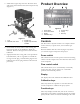
Product Overview 3. Install three bypass caps onto the all boom valves and secure them with the forks removed previously (Figure 11). 1 3 4 2 1 2 4 G013304 6 5 7 Figure 12 1. 2. 3. 4. 3 Power switch Flow control switch Display Calibration keys 5. Function keys 6. CE key 7. Enter key G013323 Figure 11 1. Fork 2. Manifold, boom valve 3. Bypass cap 4.
Enter key The console computer allows the following parameters: This key allows you to enter data into the console computer. • Area: US (acres); SI (hectares) or TU (1000 ft2) • Speed sensor type: SP1 (wheel drive, etc.), SP2 (radar), or SP3. This system uses the SP3 gear tooth sensor. Refer to Initially Programming the Console Computer on page 7. CE key This key clears the data shown in the display; it also enables you to toggle through the options found in certain function keys.
CE TOTAL AREA TOTAL VOLUME FIELD AREA FIELD VOLUME Clear Entry It clears a wrong entry; enables you to toggle between settings during initial programming; and enables you to select functions and settings. Total area sprayed It monitors the total area until you clear it to zero. Total volume of material sprayed It monitors the volume of material sprayed until you clear it to zero. Field area sprayed It monitors the total area covered until you clear it to zero.
Note: If you make a data entry error, reset the console computer by turning the power switch to the Off position and, while pressing and holding the [CE] key, turning the power switch to the On position. 4. Press the [Enter] key. 5. Press the [Boom 2 Cal] key. 6. Press the [Enter] key. 7. Enter 60. Selecting SP3 8. Press the [Enter] key. 1. Press the [CE] key until you see SP3. 9. Press the [Boom 3 Cal] key. Note: SP1 is for wheel drive and SP2 is for radar speed drive and are not used.
New SPEED Cal number = 148 x 500/ Distance readout 10. Enter the new Speed Cal number using the previous procedure. 2. Press the [Enter] key. 3. Enter the Valve Cal calibration number. Note: The initial valve calibration number for Valve Cal is 023. We recommend that you use this number for most spray applications; 063 may be helpful for small application rates. 4. Press the [Enter] key. Entering the Meter Cal Number Use the gallon calibration number for U.S. gallons per acre or U.S. gallons per 1000 sq.
Press the [Area/Hr] key. Enter the time of day based on a 24-hour day. For example, 1:30 p.m. is 13:30. You can also enter 0 to measure elapsed time. US, TI, TU, SP1, SP2, or SP3 Note: This data is lost each time the power is turned off. Press and hold the [Self Test] key.Press the [Total Area] key. To set the date, do the following: 1. Press the [Time] key. The display shows MONTH. 2. Press the [Enter] key to change the month. 3. Press the [Time] key. The display shows DAY. 4.
Entering the Mode Sequence with the Data Lock Activated Setting the Low Limit Flow Set Point and Low Limit Alarm 1. Press the key in which you wish to enter day. This is an optional feature. 2. Press the [Enter] key. If the actual volume per minute falls below this limit, the control valve stops closing, the alarm sounds, and the display flashes –LL–. Determine the low limit value with all the booms on. This value is automatically proportional to the percentage of booms that are on.
Note: The pump should increase the pressure until it reaches the desired rate if a Self Test speed has been entered. 13. Turn the Master Boom Control (foot) switch to the Off position. Note: The system stops the pump. 14. Turn the Agitation switch to the On position. Note: The system starts the pump and increases the pump speed until the pump reaches the preset agitation pressure. The system goes to this pressure when the booms are off and the pump and agitation are on. 15.
Maintenance Recommended Maintenance Schedule(s) Maintenance Service Interval Maintenance Procedure • Clean the flowmeter. (More often when using wettable powders) Every 200 hours Cleaning the Flowmeter the hex stud on the bottom of the turbine hub by 1/16 of a turn until the turbine spins freely. Service Interval: Every 200 hours/Yearly (whichever comes first) (More often when using wettable powders) Calibrating the Flowmeter 1. Thoroughly rinse and drain the entire spraying system. 1.
Corrected Meter Cal = (Meter Cal x Total Volume) / Amount of Water Corrected Meter Cal = (1660 x 103) /100 Corrected Meter Cal = 1710. Note: Repeat this procedure several times to confirm that the corrected Meter Cal number is accurate. Testing the Flowmeter Cable 1. Disconnect the console control cable from the flowmeter cable. 2. Hold the cable so that the keyway is in the 12 o’ clock position (Figure 15). 4 1 G013306 3 2 Figure 15 1. Keyway 3. Signal (6 o’clock position) 2.
Troubleshooting Note: If the console computer malfunctions or needs repair, you can resume spraying in manual mode by unplugging the cables form the rear of the console computer. You can then control the system using the center console controls. Problem No display lights with the power on Possible Cause Corrective Action 1. The fuse on the back of the console computer is blown. 1. Replace the fuse. 2. The battery connections are loose. 3. The power switch is not operating properly. 4.
Problem The rate is inaccurate or unstable Possible Cause 1. You incorrectly entered a number in the console computer. 1. Verify that all the numbers entered in the console computer are correct. 2. The wheel drive setting is not set to SP3. 3. The Speed Cal number is incorrect. 4. The Rate 1 or Rate 2 display is not constant when the speed is constant. 2. Set the wheel drive setting to SP3. 5.