
Installation Instructions
1
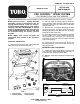
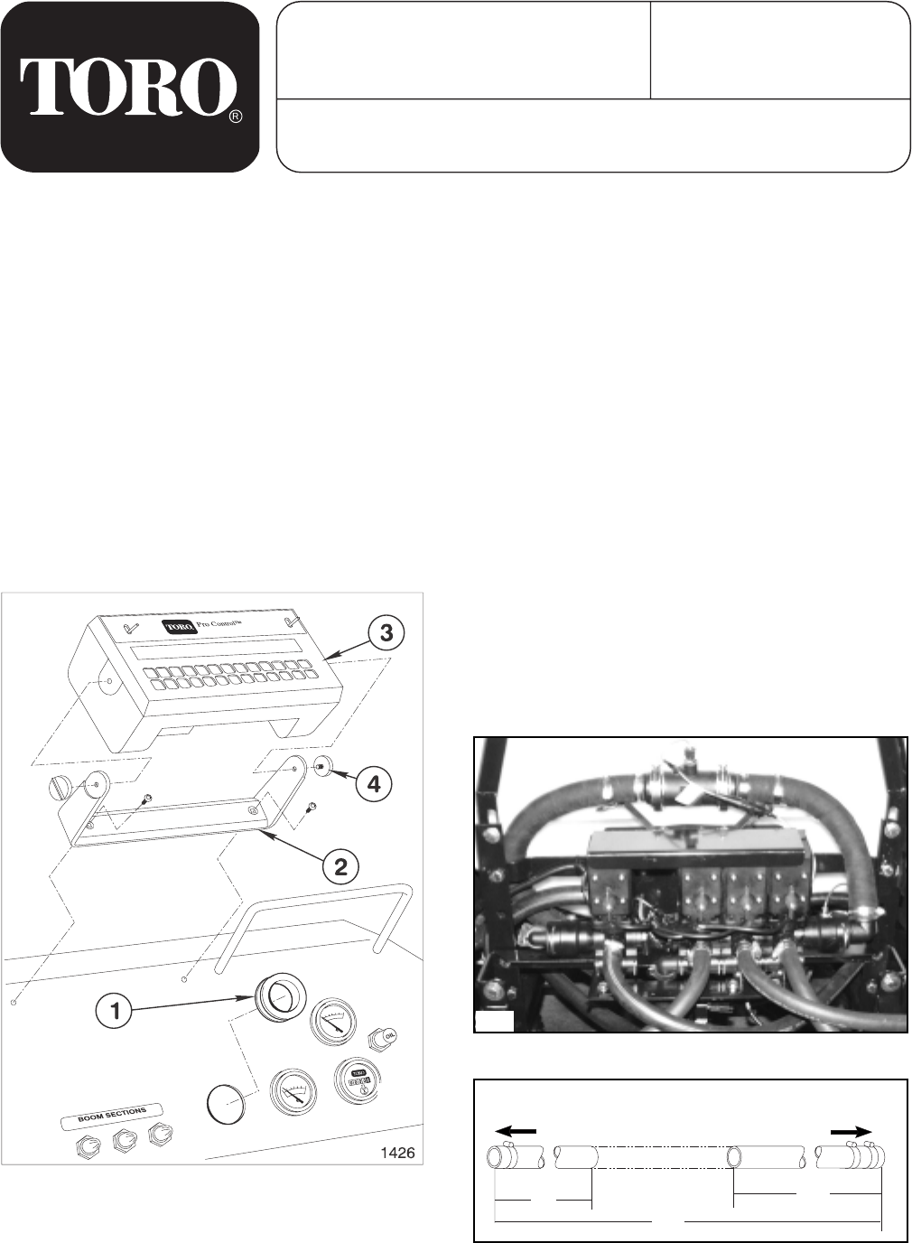
TO PUMP
TO BOOM
VALVE ASSEMBLY
27”
15”
50”
PRO CONTROL SPRAY SYSTEM
FOR THE MULTI-PRO
®
5600 TURF SPRAYER
MODEL NO. 41086
FORM NO. 104-9085 REV. A
SET-UP AND
PARTS MANUAL
Refer to the illustrated Parts List for the details of parts used in assembling the Pro Control system.
NOTE: "Right", "Left", "Front", and "Rear" are
referenced while seated in the operator's
position.
CONSOLE COMPUTER:
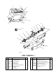
1. Remove the knockout plug in the dash and
insert the Large Grommet. See FIG. 1.
FIG. 1
1. Large Grommet 3. Control Console
2. Mounting Bracket 4. Mounting Knobs
4. Insert the Console Control Cable and Speed
Sensor cable from under dash through the
Grommeted hole, and plug into the proper
receptacle in the rear of the Computer. Secure
with Locking Rings.
5. Install the Console Computer within the
Mounting Bracket, and secure with the two (2)
Mounting Knobs.
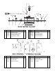
MOUNTING THE FLOW METER:
1. Locate and remove the Boom Supply hose
from the Boom Valve ASM and the Tee which is
located behind the Boom Valve ASM.
2. Measure, mark and cut Supply Hose as shown
in FIG. 3.
©The TORO Company - 2002
All Rights Reserved
1425-5600
FIG. 3
FIG. 2
2042
NOTE: The Pro Control System provides
automatic control of application rate for
varying vehicle speeds. If the Pro Control
Console should malfunction or need repairs,
spraying CAN BE CONTINUED in manual
mode by unplugging the cables from the rear
of the Computer Console. The unit can then
be controlled using the Center Console
Controls.
3. Remove the "U"-shaped Mounting Bracket
from the Console Computer and secure the
Mounting Bracket to the dash with two (2) flange
bt hd cap screws. See FIG. 1.
2. Cut one plastic tie securing the Pro Control
wiring harness under the dash. Remove the two
protective caps from the cable ends, and retain
them for later use.