
Installation Instructions


3
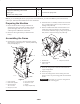
7. Connect the red power wire to the front of the solenoid
(Fig. 3), located on the left side of the engine.
1
2
Figure 3
1. Red power wire from the electrical box on the hose reel.
2. Solenoid
8. Connect the black wire to a ground terminal, located on
the back of the engine.
1
2
3
Figure 4
1. Ground terminal
2. Black wire
3. Red wire to the solenoid
Installing the Control Valve
1. Remove the hose retainer to disconnect the boom hose
from the supply tee (Fig. 5).
2
1
Figure 5
1. Supply tee 2. Hose retainer
Note: The small tube and fitting on top of the supply tee
shown in Figures 5 and 6 is not present on Workman 200
Spray Systems.
2. Remove the 2 bolts securing the supply tee and supply
tee mounting bracket to the vehicle (Fig. 6).
1
Figure 6
1. Supply tee mounting bracket