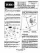
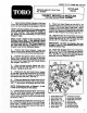
FORM REV B SET-UP AND PARTS CATALOG MODEL NO. 41120-60001 & UP MODEL NO. 41020-60001 & UP MODEL NO. 41021-60001 & UP MODEL NO. 41128-60001 & UP MODEL NO. 41118-60001 & UP MANUAL VALVE SPRAY SYSTEM FOR THE MULTI-PRO™ 1100 VEHICLE Refer to the illustrated Parts List for the details of pants used in assembling the Manual Valve Spray System, NOTE: "Right", "Left", "Front”, and "Rear" are referenced while seated in the operator's position. TACHOMETER: 1.
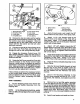
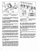
4, Remove lower rear com nut from left end of Control Naive. Attach Valve Brace and secure with flat washer and previously removed com nut. Attach other end of Valve Brace to middies soot in rear of Seat Box with 5/16" hex hd cap screw, flat washer, rock washer, and hex nut. DO NOT TORQUE OVER 30 IN LBS (3.4NM). See FIG 3. FiG. 3 1. Splash Shield 3, Valve Brace 2, Shield Brace 4.
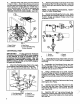
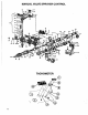
FiG. s 1. spring Mounting Angle 2. Burp Pivot Plate 3. Pump Pulley 4. Pump Brit Cover 8. Pump Cover Clamp 6. Pump Cable 7. Accessory Control 8, Pump Spring 10. Remove the hair pin cotter and flat washer from the pin in the Accessory Control Lever. Push the Control Lever down (engaged). Slide the unattached end of the Cable onto the pin and secure with the fiat washer and hair pin cotter previously removed. 11.
Barbs and 90° Hose Barb to Tee. Atlas Tee to Mounting Bracket using clang. two {(2) 5/16" flat washers, lock washers, and hex nuts. Connect x 87" Overflow Hose from rear of Tank and two x 27 -1/2" Bypass Hoses to Tee, and secure with hose clamps. FiG. 8 1. Tank Band 3.Tee 2. Clamp 4. Tee Mounting Bracket 11. Connect two (2) x Bypass Hoses to Control Valve. Secure with hose clamps.
No. 95-2067 Replaces page 5& 6 on Form INSERT "A" TO FORM NQ. 95-2067 SET-UP AND PARTS L * TURRET BODIES & NOZZLES | J coating ofgreasétometubes 1. Apply ah . -of the two Boom Mount" limbless and insert . them into the Vehicle frame as shown in FIG 10 “NOTE: Note the position of the angle member of the. Boom Mount Assemblies in relation to the tube member. They must be as shown for mountaineering of the Cross Support Angle.
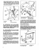
FIG. 2 1. Extension Geom Pipe | 3.. Boom Support Assembly 2. Pivot Assembly 4. Height Adjustment 12. Attach the Boom snort Assembly to the Pivot Assembly, using a 5/16" x cap screw and Jock nut. FiG 2 13." Secure the two plates of the Boom Support Assembly to one of the Extension Boom Pipes, " using two (2) 1/4" U-bolts, four {4} lock nuts and flat washers.. See FIG 3. 14, Assemble the Boom Support Assembly to the other Extension Boom Pipe. 15, -Adjust the: Booms toga level position by adjusting the.
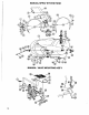
SPRAY SYSTEM PUMP COMPONENTS #1 Part No. Description Qty #1 Par No.
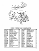
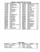
MANUAL VALVE SPRAYER CONTROL # | Part No. Description Qty Part No. Description Qty| 1 |95-2088 Section Valve "RD" Kit 3 36 93-1008 Chromium Plated Brass Bali 1 2 |95-2087 Stainless Steel Nut M4 3 37 [93-0880 Cap Nut Méx1, 25 8 3 j95-2088 8.8, Washer Dia. 4, 3x12x1 3 38 |939-1008 O-Ring Dia. 2, 62x18, 72 1 4 {95-2089 Poppet @ 39 [93-1008 Connector For Lever Pin 1 5 195-2000 Vito O-Ring Dia. 2x7 9 40 {85-2102 Control Lever 1 6 J95-2001 S.8. Washer Dia. 8, 4x14x1, 6 § 41 196-2103 Pin Dia.
MANUAL SPRAY SYSTEM TANK Rife Part No., Description Qty Ref | Part No, Description Qty il 42083 old-In Brave Assembly 2 23 143068 Fly Nut, 2° NPT ki 2 (32176 [Hex Nut, 5/18 NC | 124 43067 [Sealing Washer 1 3 [SSE-23 [Flat Washer, 816 4 25 143066 [Bulk Head, 2" NPT 1 4 920010 U-Bolt, 174 NC 4] 26 41800 [Tank Fitting, 1° NPT {f/w Tank Says} | 1 5 42198 Rubber Hold-Down 3 27 41307 90° 8.
MANUAL SPRAY VALVE SET-UP # | Part No. Description Qly # | Part No. Description Qyl 1 Ja1308 Hose Barb, TEMPT x 1 B [92-0012 Hose Barb, TEMPT x 1"HB 1 2 ja1az7 Hose Clamp 7 ¢ ]93-0888 Hose Cover 1 3 [93-0883 Hosea 10 [93-0881 Hose-supply, Bypass to Tank, x 67* 11 j92-0045 Hose Clamp # 4 j03-0851 Hose Barb, x 2 12 {o7791 Boom Fed Hose, RH 132* 1 5 je3.0888 Tee, NPT 1 13 193-0884 Hose Cover, 1.
INSERT "B* TO FORM NO. 95-2067 NOTE: THIS SHEET REPLACES PAGE 13, FOR THE MANUAL VALVE SPRAY SYSTEM (MODEL NO. 41118). WHEN ORDERING A REPLACEMENT MANUAL, REQUEST FORM NO. 95-8307. NOZZLE BODIES & BOOM HOSES Ref. | Part No. Description Q. Ref. | Part No. Description Qty. * 1959183 Turret Body Double Bark 7 15 | 95.9201 Single Hose Barb 1 (Incl. Ref, #'s 1-14) 16 |95-8187 Nozzle Dust Cap 22 * | 95-9181 Turret Body Single Bark 3 {Incl, Ref. #17) {Incl. Ret.
BOOM FRAME He fl Part No. Description Hef [Part No. Description 1t 42223 Tube Wedge Says [24* | 42196 impression spring 2 321536 l Lock Nut, 42706 Breakaway Pivot Says B 42225 [Cross Support Angle 126" 1 321121-springing Pin, 1/4.x 2 413258 HHS, 12 NC x 114" 27 |3256-23 [Fiat Washer, 5/16 STAEL. 5 42258 [Spacer Tubs, Ig.
CENTRIFUGAL PUMP (93-0848) Ret! Part No. | Description Qty! Ref| Part No. | Description [Oty] 1 [42084 Drain Plug 4 -0926 counting Flange 1 2 3-0822 [Pump Casting 1 10 3236 ot 4 B 42086 impeller Nut 1 11 93-0927 all Bearing R [4 193-0923 impeller {Polypropylene) 1 12 p-0928 oy 1 [42089 -Ring 1 13 -0920 Pump Shaft 1 142088 mechanical Seal Vito 1 14 193-0830 oy . 1 193-0924 [Seal Retainer 1 15 le2003 ring Retainer 1 42002 linger Ring 1 16 [93-0931 casket 1 * -8520 oal Kit (Incl.