
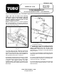
Installation Instructions


1
FORM NO. 42901
MODEL NO. 41124
SET-UP AND
PARTS LIST
FOAM MARKER KIT
for use on the MULTI-PRO
TM
1100 VEHICLE
Refer to the illustrated Parts List for the details of parts used in assembling the FOAM MARKER KIT.
FIG. 1
NOTE: If installing this Kit on a vehicle equipped
with "Enclosed Boom," work these instructions
with the "Enclosed Boom" Instructions found in
the Set-up and Parts manual.
"Right" and "Left" as used in the following
instructions, refer to the operator's right and
left when seated in the normal operating
position. Likewise, "Front" and "Rear" as seen
from the operator's position.
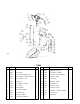
FIG. 2
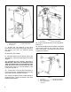
1. 90° Hose Barb 3. 9/32" Drilled Hole
2. Split Eyelet Connector
©The TORO Company - 1999
All Rights Reserved
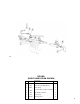
1. Locate, mark and drill, DRILLING THROUGH
THE TOP SURFACE ONLY, one 9/32" dia. hole at
8-inches from the ends of the right and left Boom
Pipes. These holes are used for the installation of
the Split Eyelet Connectors. See FIG. 1.
2. Assemble the Split Eyelet Connector around
the Boom Pipe as shown in FIG. 2. Align the hole
in the Split Eyelet Connector with the hole drilled
in Step 1, and tighten securely. DO NOT
OVERTIGHTEN. Install the 90° hose barb into the
Split Eyelet Connector. Repeat steps for opposite
Boom Pipe.
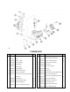
3. Assemble the Compressor complete. See page
4. IMPORTANT! Make sure the BRASS Check
Valve is installed at the Tee on top of the
Compressor. Remove the rear Console Panel
and mount the Compressor to the side panel as
shown in FIG. 3.
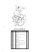
4. Install the ON/OFF Switch in the dash panel and
attach the push-on terminal of the orange wire to
the Switch.
5. Insert the stripped end of the Compressor wire
into the butt splice connector on the orange wire.
Crimp the connector. See page 4.
6. Connect the push-on terminal of the brown wire
(from the Vehicle Wiring Harness) to the other
Switch terminal.
1. Boom Pipe
1488
1489