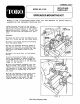
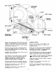
MODEL NO. 41152 FORM NO. 43011 SET-UP AND PARTS LIST SPREADER MOUNTING KIT Refer to the illustrated Parts List for the details of parts used in assembling the Spreader Mounting Kit. Sprig He “and“Left as used in the follows ing instructions, refer to the operator’s right and left when seated in the normal operating position, Likewise, "Front" and “Rear” as seen from the operator’'s position. ASSEMBLY: # Detach the Drive Cover by removing the four 5/16" bolts and set the Cover aside.
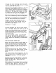
+ WITH THE ENGINE TURNED Offs ® Align the rear mounting plate as shown in FIG. 3 and secure with bolt, four washers and a hex nut, ® Secure the Spreader Assembly to the two Mounting Frame uprights with two 5/8 x bolts, hex nuts and eight washers. NOTE: If necessary, loosen bolts holding uprights to the Mounting Frame, in order to align the holes in the uprights with the holes in the lugs on the Hopper.
| APPROX. B BELT GUIDE~ SPREADER PULLEY BELT GUIDE IDLER PULLEY {engaged) ~ ENGINE PULLEY BELT GUIDE —J PIVOT BOLT { MOUNTING — PLATE BOLT PIVOTING BELT GUIDE FIG. Adjust the *pivoting” Belt Guide so that there is approximately 1/8 inch clearance between it and the Drive Belt, when the bottom of the Belt is drawn tight between the Pulleys. See FIG. 5. a Loosen the pivot bolt and apply press-— ure to the upper portion of the Belt to draw the bottom portion of the Belt tight between the Pulleys.
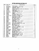
SPREADER MOUNTING KIT DESCRIPTION i b 8 guise B30 LT LTI SCI LA = D00 DM LN EAD 0 I IR RIS COIN IO WIS DNO00 TV (R bt CRD GO IO NIt LTI 0 s o 5000 1530 MINI RS GIANNINI BBB MINI NI o 3 NIN s s BIND CI HA TEED LIS RIS Y RO | Drive Cover Flat w Washer, 5/16 5/16 NC Spreader Cable . QLT Pin Cotter .o Clutch Control Handle (&/w Vehicle Clevis Pin o Hair Pin Cotter Guide Lug LAt e sett et Flat Washer, 3/8 STAEL. "Il . ..