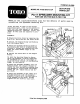
MODEL NO. 41152-30101 & UP FORM NO. 92-0392 SET-UP AND PARTS LIST PA-17 SPREADER MOUNTING KIT FOR USE ON THE MULTI-PRO 1100 Refer to the illustrated Parts List for the details of parts used in assembling the Spreader Mounting Kit. “Right and*Left as used in the follow. ing instructions, refer to the operator‘s right and left when seated in the normal operating position. Likewise, "Front® and “Rear"” as seen from the operator’s position.
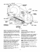
® Align the rear mounting plate as shown in FIJI. 3 and secure with bolt, four washers and a hex nut. ® Secure the Spreader Assembly to the two Mounting Frame uprights with two 5/8 x bolts, hex nuts and eight washers. NOTE: If necessary, loosen bolts holding uprights to the Mounting Frame, in order to align the holes in the uprights with the holes in the lugs on the Hopper.
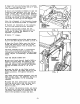
BELT GUIDE BELT GUIDE {IDLER PULLEY engaged) — ENGINE PULLEY BELT GUIDE J PIVOT: BOLT MOUNTING PLATE BOLT PIVOTING BELT GUIDE FIG. Adjust the *pivoting® Belt Guide so that there is approximately 1/8 inch clearance between it and tha Drive Belt, when the bottom of the Belt is drawn tight between the Pulleys. See FIG. 5. M Loosen the pivot bolt and apply precise ure to the upper portion of the Belt to draw the bottom portion of the Belt tight between the Pulleys.
GEAR MULTIPLIER, 5:1 REF PART NO. DESCRIPTION QTY 1 43047 250 Housing Half 1 2 43048 250 Housing Half 1 3 43048 250 Gear, INT HEL LH, 157 1 4 43050 250 Gear, HEL RH, 75T 1 5 43051 250 Shim, .002 Red 2 6 43052 250 Shim, .005 Blue 2 7 43053 Spec. Shaft Output 1 8 43054 Ball Bearing irreverent 2 9 43055 Cup Bearing cease 2 10 43056 Cone Bearing 2 11 20-50-GAD HHS 3/4% {Grade 5) 4 12 43057 Key, 3/16 43058 Lowell Pin, 43061 Seal Severeness 1 15 43060 S Al 1 16 43059 Skt.