Form No. 3360-892 Rev B Sonic Boom Kit for Multi-Pro Turf Sprayers Model No. 41217—Serial No. 280000201 and Up Installation Instructions Safety Safety and Instructional Decals Safety decals and instructions are easily visible to the operator and are located near any area of potential danger. Replace any decal that is damaged or lost. 93-8053 1. Read the Operator’s Manual. 94-8604 94-8576 94-8582 © 2008—The Toro® Company 8111 Lyndale Avenue South Bloomington, MN 55420 Register at www.Toro.com.
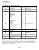
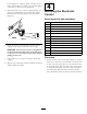
Installation Loose Parts Use the chart below to verify that all parts have been shipped. Procedure 1 2 3 4 5 6 7 8 Description Use Qty. No parts required – Prepare the machine.
1 Preparing the Machine No Parts Required Procedure Position the machine on a level surface, stop the engine, remove the ignition key and engage parking brake. If you leave the key in the ignition switch, someone could accidently start the engine and seriously injure you or other bystanders. Remove the key from the ignition switch before you do any maintenance.
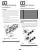
2 3 Removing the Hardstops Installing the Ultrasonic Sensors No Parts Required Parts needed for this procedure: Procedure If your machine has hardstops installed, they must be removed before installing the Sonic Boom Kit. The hardstops are located in the center boom of the caged booms and can be seen when the booms are in the upright, transport position. If your machine does not have hardstops installed, or is the older, rail style booms skip the next procedure. 1.
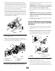
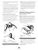
3. Install the protection tube around the ultrasonic sensor with the angled side facing inward, toward the vehicle. Lightly secure the protection tube to the boom (Figure 2), using 2 U-bolts, 4 washers (5/16 inch), and 4 locknuts (1/4 inch). Do not fully tighten at this time to allow for later adjustment. 4.
boom (Figure 5), using 2 U-bolts, 4 washers (5/16 inch), and 4 locknuts (1/4 inch). Do not fully tighten at this time to allow for later adjustment. 4 5. Rotate the sensor up so that it is approximately 10 degrees off parallel with the ground, then tighten the locknuts on the U-bolts to secure the sensor (Figure 6). Mounting the Electronic Control Parts needed for this procedure: Figure 6 6. Route the sensor wire along the top of the boom support to the center of the center boom pipe.
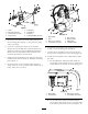
Figure 7 1. 2. 3. 4. Relay Bolt (1/4 x 5/8 inch) Lock washer (1/4 inch) Nut (1/4 inch) 5. 6. 7. 8. Fuse block Screw (#10) Nut (#10) Thermal breaker (30 Amp) Figure 8 1. 2. 3. 4. 2. Secure the fuse block end of the wiring harness to the mounting plate (Figure 7), using 2 screws (#10) and 2 nuts (#10). Mount plate ECU Bolt (1/4 x 2-1/2 inch) Lock washer (1/4 inch) 5. 6. 7. 8. Nut (1/4 inch) Wiring harness Relay leads Controller leads 3. Locate the existing fuse block on the machine.
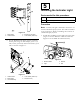
5 Installing the Indicator Light Parts needed for this procedure: 1 Decal, 94-8582 1 Light assembly Procedure Note: A smaller, red light is included in the kit for use with the Workman Spray System. This will be installed to the control box. Refer to Installing the Controls on a Workman Spray System. Figure 10 1. Mount plate 2. Vehicle frame 3. Bolt (5/16 x 3/4 inch) 4. Lock washer (5/16 inch) 1.
1. Remove the spray control panel to expose the bottom side (Figure 14 for the 1250 and Figure 15 for the 1200). Figure 13 1. Decal 94-8582 2. Light Figure 14 3. Washer 4. Nut 1. Plug 2. Switch 3. Notch (at back) 4. Spray control panel 2. Remove the nut and washer from the bottom of the light. 3. Install the light in the dash and secure it using the washer and nut (Figure 12 or Figure 13). 4. Connect the 2 spade connectors on a separate branch of the wiring harness to the posts on the light.
Note: The load side can be determined by testing both solenoid posts when the ignition is turned off. The hot side will read approximately 12V , while the load side has no voltage. The load side can be confirmed by turning the ignition to the run or On position and testing the load side again. The load side will read approximately 12V with the ignition on. Turn the ignition to Off and remove the key before continuing with any of the installation or maintenance. 4.
1. Route the branch of the sonic boom wire harness with the three large connectors into the control panel area. 2. If boom lift switches are installed remove any existing connectors plugged into the lift switches. 3. Connect the connector with green and white, green and black, and black wires to the bottom of the right boom lift switch. 4. Connect the connector with blue and white, blue and black, and black wires to the bottom of the left boom lift switch. 5.
Figure 19 1. Spray control panel 2. Screws 3. Drilled hole, 0.375 inch diameter hole 4. Sonic boom plug 3. Install the indicator light through the back of the hole. Secure it to the front panel with the fasteners included (Figure 20). 4. Remove the sonic boom switch plug from the front panel and install the sonic boom rocker switch (Figure 20). Figure 20 1. Spray control panel 2. Sonic boom plug 3. Existing boom lift switches 4. Existing boom lift connectors 5. Indicator light, install 6.
5. Connect the connector with blue/white, blue/black, and black wires to the bottom of the left boom lift switch. 6. Connect the connector with purple, white, yellow, and black wires to the bottom of the sonic boom switch. 7. Connect the light indicator to the wiring harness with two spade connectors. 8. Install the front control panel cover to the control box using the fasteners removed previously (Figure 19). 9.
7 8 Connecting the Wiring to the Sensors and Actuators Calibrating the Sonic Booms No Parts Required Parts needed for this procedure: 2 Procedure Conversion wires (Older boom lifts only) 1. Park the sprayer in an open, level turf area that is free of trees, buildings, vehicles, debris, and underground utilities and plumbing. Procedure 1. Ensure that the wire harness is routed to the back of the vehicle along the path of the other wires and hoses. 2. Set the Sonic Boom switch to the manual position.
Operation • Remove and rotate the cover 180 degrees. Affix it to the top side of the sensor when sonic boom is in use. Using the Controls • Install the cover to protect the ultrasonic senor when not in use, booms are placed in the transport position, and/or in storage. Sonic Boom switch—this switch has 3 settings: Automatic, Off, and Manual (Figure 23), as follows: • Automatic—enables the automatic movement of the booms.
Maintenance Cleaning Clean the sensors periodically with a damp cloth. When you clean the sensors, inspect the foam sensor filter. If it is damaged or excessively dirty, replace it. Important: Do not spray water at or on the sensors. Water sprayed under even household pressure can damage the sensor. Always cover the sensors completely before washing the sprayer. Remove covers to remove any trapped moisture. Wipe the insides of the covers clean and dry before installing the over the sensors.
Troubleshooting Problem Possible Cause Corrective Action One or both booms malfunction; the Sonic Boom light is Off. 1. A fuse is blown. 1. Replace the fuse. 2. The light is burned out. 3. The electronic controller or wiring is damaged. 2. Replace the light. 3. Contact your Authorized Toro Distributor. One or both booms malfunction; the Sonic Boom light flashes slowly. 1. There is a minor system error. 1. Lower the affected boom(s) using the boom switch(es) to clear the error. 2.
Notes: 18
Notes: 19