
Installation Instructions
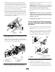


4.Connecttheconnectorwithblueandwhite,blue
andblack,andblackwirestothebottomoftheleft
boomliftswitch.
5.Connecttheconnectorwithpurple,yellow ,andblack
wirestothebottomofthesonicboomswitch.
6.Routethefreeendofthewiringharnessdown
throughtheoorandrearward,followingthespray
systemwireharnesstothecenterboomassemblyat
thebackofthevehicle.Usecabletiestosecurethe
wiringharnesstotheotherwiringharnessesaway
fromtheengineandmovingparts.
7.Installthespraycontrolpanelandsecureitwiththe
fastenersremovedpreviously.
ConnectingtheWiringtotheFuseBlock
1.Routethebranchofthesonicboomwiringharness
withthesmallspadeconnectorandaringorfork
terminalintotheseatboxandtothefusearea.
2.Lifttheseattoaccessthefusearea.Locatethe
auxiliarysolenoidandgroundterminalblock.
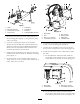
3.Connecttheringlabeledgroundontheblackwireto
thegroundterminalblock(Figure16).
Figure16
1.Blackwire3.Redwire
2.Groundterminalblock
4.Auxiliarysolenoid
4.Connecttheredwiretotheloadsideoftheauxiliary
solenoid.
Note:Theloadsidecanbedeterminedbytesting
bothsolenoidpostswhentheignitionisturnedoff.
Thehotsidewillreadapproximately12V,while
theloadsidehasnovoltage.Theloadsidecanbe
conrmedbyturningtheignitiontotherunorOn
positionandtestingtheloadsideagain.Theload
sidewillreadapproximately12Vwiththeignition
on.TurntheignitiontoOffandremovethekey
beforecontinuingwithanyoftheinstallationor
maintenance.
5.Lowertheseat.
InstallingtheControlsonaMultiPro
5600or5700-DTurfSprayer
InstallingtheSwitches
Note:Thefollowingprocedureassumesboomlift
switchesareinstalledonthemachine.Formachines
withoutboomliftswitchesorifyouhavenotalready
installedtheswitchesfromtheElectricBoomLift
Kit,installthoseswitchesnowasdescribedinthe
instructionswiththatkit.Donotinstallthewireharness
thancomeswiththeElectricBoomLiftKit.
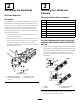
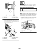
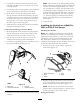
1.Removethespraycontrolpaneltoexposethe
bottomside(Figure17).
Figure17
1.Spraycontrolpanel
4.Plug
2.Latch5.Notch
3.Switch
2.Removethepluginthesonicboomslotfromthe
spraycontrolpanelonthevehicleandinstallthe
rockerswitchprovidedinitsplace(Figure17).
Note:Ensurethattheorientationoftheswitch
matcheswhatisshowninFigure17,withthenotch
pointingtowardthefrontofthevehicle.
WiringtheSwitches
10