
Installation Instructions
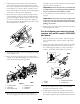


3.Installtheprotectiontubearoundtheultrasonic
sensorwiththeangledsidefacinginward,toward
thevehicle.Lightlysecuretheprotectiontubetothe
boom(Figure2),using2U-bolts,4washers(5/16
inch),and4locknuts(1/4inch).Donotfullytighten
atthistimetoallowforlateradjustment.
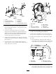
4.Rotatethesensorandprotectiontubeupsothatit
isapproximately25degreesaboveparallelwiththe
ground,thentightenallthelocknutsontheU-bolts
tosecurethesensorandprojectiontube(Figure3).
Theprotectiontubeshouldremainabovethesensor
whenadjustmentiscomplete.
Figure3
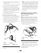
5.Threadtheultrasonicsensorwirethroughthestrap
oftherubbercover.
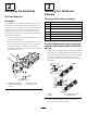
6.Routethesensorwirealongthetopoftheboom
supporttotheslideblock(Figure4).Secureittothe
topoftheboomusingclipsprovided.
Figure4
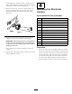
1.Extensionboom
4.Wirefromsensor
2.Wireclips
5.Slideblock
3.Boomsupplyhose
6.Cabletie
7.Routethesensorwirebelowtheslideblockto
theboomsupplyhoseandontothecenterboom
assembly.Securethewireharnesstotheboomhose
withthecableties(Figure4).
Important:Ensurethatthewireisroutedbelow
theslideblocktoavoidbeingpinchedwhenthe
boomsareplacedinthetransportcradle.
8.Use5cabletiestosecuretheharnesstotheboom
support.
Important:Ensurethatyouleaveenoughslack
inthewirenearthejointoftheextensionboom
sothatyoucanraiseandlowertheboomwithout
pullingonthewire.
9.Repeatsteps1through8fortheleftboomextension
andleftultrasonicsensor.
Usethefollowingprocedureforboom
systemswithserialnumber259999999
andbelow.
1.Parkthesprayeronaatsurface,lowerthebooms,
settheparkingbrake,stoptheengine,andremove
thekey.
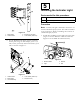
2.Lightlysecuretherightultrasonicsensortotheright
boompipehalfwaybetweenthelastnozzleand
theverticalsupport(Figure5),using2U-bolts,4
washers(5/16inch),and4locknuts(1/4inch).
Figure5
1.Sensor
3.Locknutsandwashers
2.U-bolts4.Protectionbar
3.Installtherubbersensorcovertothethreaded
portionoftheultrasonicsensor.
4.Installtheprotectiontubearoundtheultrasonic
sensorwiththeangledsidefacinginward,toward
thevehicle.Lightlysecuretheprotectiontubetothe
5