
Installation Instructions
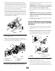


boom(Figure5),using2U-bolts,4washers(5/16
inch),and4locknuts(1/4inch).Donotfullytighten
atthistimetoallowforlateradjustment.
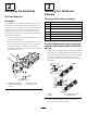
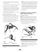
5.Rotatethesensorupsothatitisapproximately10
degreesoffparallelwiththeground,thentighten
thelocknutsontheU-boltstosecurethesensor
(Figure6).
Figure6
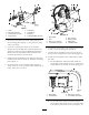
6.Routethesensorwirealongthetopoftheboom
supporttothecenterofthecenterboompipe.
Important:Ensurethatyouleaveenoughslack
inthewirenearthejointoftheextensionboom
sothatyoucanraiseandlowertheboomwithout
pullingonthewire.
7.Use5cabletiestosecurethetubingtotheboom
support.
8.Repeatsteps2through7fortheleftboomextension
andleftultrasonicsensor.
4
MountingtheElectronic
Control
Partsneededforthisprocedure:
1Mountplate
6Relay
4
Bolt(1/4x5/8inch)
8
Lockwasher(1/4inch)
8
Nut(1/4inch)
1Wireharness
2
Screw(#10)
2
Nut(#10)
1
ElectronicControlUnit(ECU)
4
Bolt(1/4x2-1/2inch)
2
Bolt(5/16x3/4inch)
2
Lockwasher(5/16inch)
2U-boltclamps
4
Nut(5/16inch)
Procedure
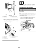
1.Secure6relaystothemountplate(Figure7),using4
bolts(1/4x5/8inch),4lockwashers(1/4inch),and
4nuts(1/4inch).Fourrelayscanbemountedtothe
frontoftheplate,whiletworelayshavetomounted
tothebackoftheplate.Thetworelaysmountedto
thebackoftheplatewillsharefastenerswiththe
relaymountedtothefrontatthesameholelocation
6