
Installation Instructions
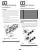
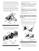
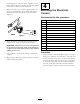
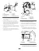
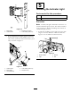

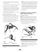

Figure7
1.Relay5.Fuseblock
2.Bolt(1/4x5/8inch)6.Screw(#10)
3.Lockwasher(1/4inch)7.Nut(#10)
4.Nut(1/4inch)8.Thermalbreaker(30Amp)
2.Securethefuseblockendofthewiringharnessto
themountingplate(Figure7),using2screws(#10)
and2nuts(#10).
3.Locatetheexistingfuseblockonthemachine.
(BelowtheseatforMP1200,1250and5000series
machines;underthedashforWorkmanmachines.)
Removethetwothermalbreakersinstalledatthe
boomliftpositionsinthefuseblock.
4.Installtwothermalbreakers(30Amp)intotheopen,
middleslotsinthefuseblockontheECUmounting
plate(Figure7).
5.SecuretheECUtothemountingplate(Figure8),
using4bolts(1/4x2-1/2inch),4lockwashers(1/4
inch),and4nuts(1/4inch).
Figure8
1.Mountplate
5.Nut(1/4inch)
2.ECU
6.Wiringharness
3.Bolt(1/4x2-1/2inch)
7.Relayleads
4.Lockwasher(1/4inch)8.Controllerleads
6.Connecttherelayleadsonthewiringharnesstothe
6relaysonthemountingplate(Figure8).
7.Connectthe2controllerleads(onelongandone
short)onthewiringharnesstotheECU(Figure8).
8.Installthemountplatetothevehicleframe,under
thedash.
A.FortheMulti-Pro1200and1250,installthe
mountplateusing2bolts(5/16x3/4inch)and
2lockwashers(5/16inch)asshowninFigure9.
Figure9
1.Mountplate
3.Bolt(5/16x3/4inch)
2.Vehicleframe4.Lockwasher(5/16inch)
B.FortheMultiPro5600and5700installthe
mountplateusing2bolts(5/16x3/4inch)and2
lockwashers(5/16inch)asshowninFigure10.
7