Form No. 3365-202 Rev A Sonic Boom Kit for Multi-Pro Turf Sprayers Model No. 41217—Serial No. 310000001 and Up Installation Instructions This attachment maintains consistent distances from the boom nozzles to the ground when spraying over uneven surfaces and is intended to be used by professional, hired operators in commercial applications. It is primarily designed for spraying golf course applications, parks, sports fields, and on commercial grounds.
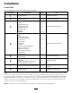
Installation Loose Parts Use the chart below to verify that all parts have been shipped. Procedure 1 2 3 4 5 6 7 8 Description Use Qty. No parts required – Prepare the machine.
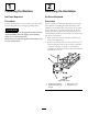
1 2 Preparing the Machine Removing the Hardstops No Parts Required No Parts Required Procedure Procedure Position the machine on a level surface, stop the engine, remove the ignition key and engage parking brake. If your machine has hardstops installed, they must be removed before installing the Sonic Boom Kit. The hardstops are located in the center boom of the caged booms and can be seen when the booms are in the upright, transport position.
3. Install the protection tube around the ultrasonic sensor with the angled side facing inward, toward the vehicle. Lightly secure the protection tube to the boom (Figure 2), using 2 U-bolts, 4 washers (5/16 inch), and 4 locknuts (1/4 inch). Do not fully tighten at this time to allow for later adjustment. 4.
assembly. Secure the wire harness to the boom hose with the cable ties (Figure 4). inch), and 4 locknuts (1/4 inch). Do not fully tighten at this time to allow for later adjustment. 5. Rotate the sensor up so that it is approximately 10 degrees off parallel with the ground, then tighten the locknuts on the U-bolts to secure the sensor (Figure 6). Important: Ensure that the wire is routed below the slide block to avoid being pinched when the booms are placed in the transport cradle. 8.
4 Mounting the Electronic Control Parts needed for this procedure: 1 Mount plate 6 Relay 4 Bolt (1/4 x 5/8 inch) 8 Lock washer (1/4 inch) 8 Nut (1/4 inch) 1 Wire harness 2 Screw (#10) 2 Nut (#10) 1 Electronic Control Unit (ECU) 4 Bolt (1/4 x 2-1/2 inch) 2 Bolt (5/16 x 3/4 inch) 2 Lock washer (5/16 inch) 2 U-bolt clamps 4 Nut (5/16 inch) Figure 7 1. 2. 3. 4. Relay Bolt (1/4 x 5/8 inch) Lock washer (1/4 inch) Nut (1/4 inch) 5. 6. 7. 8.
Figure 8 1. 2. 3. 4. Mount plate ECU Bolt (1/4 x 2-1/2 inch) Lock washer (1/4 inch) 5. 6. 7. 8. Figure 10 Nut (1/4 inch) Wiring harness Relay leads Controller leads 1. Mount plate 2. Vehicle frame 3. Bolt (5/16 x 3/4 inch) 4. Lock washer (5/16 inch) C. For the Workman 200 Spray System, install the mount plate using 2 U-bolt clamps (5/16 x 3/4 inch) 2 nuts (5/16 inch) and 2 lock washers (5/16 inch) as shown in Figure 11. 6.
5 Installing the Indicator Light Parts needed for this procedure: 1 Decal, 94-8582 1 Light assembly Procedure Note: A smaller, red light is included in the kit for use with the Workman Spray System. This will be installed to the control box. Refer to Installing the Controls on a Workman Spray System. Figure 13 1. Decal 94-8582 2. Light 1. Install decal 94-8582 over the light hole in the dash (Figure 12 for the Multi Pro 1200 and 1250 and Figure 13 for the Multi Pro 5600 and 5700). 3. Washer 4.
1. Remove the spray control panel to expose the bottom side (Figure 14 for the 1250 and Figure 15 for the 1200). 4. Connect the connector with blue and white, blue and black, and black wires to the bottom of the left boom lift switch. 5. Connect the connector with purple, yellow, and black wires to the bottom of the sonic boom switch. 6.
Note: The load side can be determined by testing both solenoid posts when the ignition is turned off. The hot side will read approximately 12V , while the load side has no voltage. The load side can be confirmed by turning the ignition to the run or On position and testing the load side again. The load side will read approximately 12V with the ignition on. Turn the ignition to Off and remove the key before continuing with any of the installation or maintenance. 1.
Figure 19 1. Spray control panel 2. Screws 3. Drilled hole, 0.375 inch diameter hole 4. Sonic boom plug 3. Install the indicator light through the back of the hole. Secure it to the front panel with the fasteners included (Figure 20). Figure 18 1. Black wire 2. Ground terminal block 4. Remove the sonic boom switch plug from the front panel and install the sonic boom rocker switch (Figure 20). 3. Red wire 4. Auxiliary solenoid 4.
Figure 21 1. Switch, with notch in the rear 2. Remove the cover 4. Existing boom lift connectors 4. Install cover, notch in the front C. Holding the switch cover in position, flip the switch body 180 degrees so that the connector notch is front left corner (Figure 21). Figure 20 1. Spray control panel 2. Sonic boom plug 3. Existing boom lift switches 3. Switch body, rotated 180° D.
5. Connect the connector with blue/white, blue/black, and black wires to the bottom of the left boom lift switch. 7 6. Connect the connector with purple, white, yellow, and black wires to the bottom of the sonic boom switch. Connecting the Wiring to the Sensors and Actuators 7. Connect the light indicator to the wiring harness with two spade connectors. Parts needed for this procedure: 8. Install the front control panel cover to the control box using the fasteners removed previously (Figure 19).
Operation 8 Using the Controls Calibrating the Sonic Booms Sonic Boom switch—this switch has 3 settings: Automatic, Off, and Manual (Figure 23), as follows: No Parts Required • Automatic—enables the automatic movement of the booms. When in automatic mode the booms adjust so that the tips of the booms remain the same distance from the ground. Procedure 1. Park the sprayer in an open, level turf area that is free of trees, buildings, vehicles, debris, and underground utilities and plumbing.
Maintenance • Remove and rotate the cover 180 degrees. Affix it to the top side of the sensor when sonic boom is in use. Cleaning • Install the cover to protect the ultrasonic senor when not in use, booms are placed in the transport position, and/or in storage. Clean the sensors periodically with a damp cloth. When you clean the sensors, inspect the foam sensor filter. If it is damaged or excessively dirty, replace it. Important: Do not spray water at or on the sensors.
Troubleshooting Problem Possible Cause Corrective Action One or both booms malfunction; the Sonic Boom light is Off. 1. A fuse is blown. 1. Replace the fuse. 2. The light is burned out. 3. The electronic controller or wiring is damaged. 2. Replace the light. 3. Contact your Authorized Toro Distributor. One or both booms malfunction; the Sonic Boom light flashes slowly. 1. There is a minor system error. 1. Lower the affected boom(s) using the boom switch(es) to clear the error. 2.
Schematics G013000 Electrical (Rev.
Notes: 18
Notes: 19