Sonic Boom Kit Form No. 3354-145 Rev B For Multi-Pro Turf Sprayers Model No. 41217—Serial No. 260000001 and Up Installation Instructions Safety Safety and Instructional Decals Safety decals and instructions are easily visible to the operator and are located near any area of potential danger. Replace any decal that is damaged or lost. 93-8053 1. Read the Operator’s Manual. 94-8604 94-8576 94-8582 © 2005—The Toro® Company 8111 Lyndale Avenue South Bloomington, MN 55420 Register at www.Toro.com.
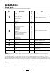
Installation Loose Parts Use the chart below to verify that all parts have been shipped. Step 1 2 3 4 6 7 8 Qty.
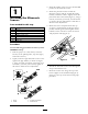
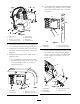
Step 3. Install the rubber sensor cover to the threaded portion of the ultrasonic sensor. 1 4. Install the protection tube around the ultrasonic sensor with the angled side facing inward, toward the vehicle. Lightly secure the protection tube to the boom (Figure 1), using 2 U-bolts, 4 washers (5/16 inch), and 4 locknuts (1/4 inch). Do not fully tighten at this time to allow for later adjustment. Installing the Ultrasonic Sensors Parts needed for this step: 2 8 8 8 2 2 4 10 5.
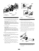
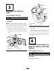
Figure 3 1. Extension boom 2. Wire clips 3. Boom supply hose 4. 5. 6. Wire from sensor Slide block Cable tie Figure 4 1. Sensor 2. U-bolts 8. Route the sensor wire below the slide block to the boom supply hose and on to the center boom assembly. Secure the wire harness to the boom hose with the cable ties (Figure 3). 3. 4. Locknuts and washers Protection bar 3. Install the rubber sensor cover to the threaded portion of the ultrasonic sensor.
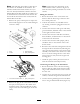
Important: Ensure that you leave enough slack in the wire near the joint of the extension boom so that you can raise and lower the boom without pulling on the wire. 7. Use 5 cable ties to secure the tubing to the boom support. 8. Repeat steps 2 through 7 for the left boom extension and left ultrasonic sensor. Step 2 Figure 6 1. 2. 3. 4. Mounting the Electronic Control 5. 6. 7. 8. Fuse block Screw (#10) Nut (#10) Thermal breaker (30 Amp) 2.
B. For the Multi Pro 5600 and 5700 install the mount plate using 2 bolts (5/16 x 3/4 inch) and 2 lock washers (5/16 inch) as shown in Figure 9. Figure 7 1. 2. 3. 4. Mount plate ECU Bolt (1/4 x 2-1/2 inch) Lock washer (1/4 inch) 5. 6. 7. 8. Nut (1/4 inch) Wiring harness Relay leads Controller leads Figure 9 6. Connect the relay leads on the wiring harness to the 6 relays on the mounting plate (Figure 7). 1. Mount plate 2. Vehicle frame 7.
Step 3 Installing the Indicator Light Parts needed for this step: 1 1 Decal, 94-8582 Light assembly Procedure Figure 12 Note: A smaller, red light is included in the kit for use with the Workman Spray System. This will be installed to the control box. Refer to Installing the Controls on a Workman Spray System. 1. 2. Decal 94-8582 Light 3. 4. Washer Nut 2. Remove the nut and washer from the bottom of the light. 1.
Note: The following procedure assumes boom lift switches are installed on the machine. For machines without boom lift switches or if you have not already installed the switches from the Electric Boom Lift Kit, install those switches now as described in the instructions with that kit. Do not install the wire harness than comes with the Electric Boom Lift Kit. Note: Ensure that the orientation of the switch matches what is shown in Figure 13, with the notch pointing toward the rear of the vehicle.
Step 5 Installing the Controls on a Multi Pro 5600 or 5700-D Turf Sprayer No Parts Required Procedure Installing the Switches Note: The following procedure assumes boom lift switches are installed on the machine. For machines without boom lift switches or if you have not already installed the switches from the Electric Boom Lift Kit, install those switches now as described in the instructions with that kit. Do not install the wire harness than comes with the Electric Boom Lift Kit. 1.
Wiring the Switches 1. Route the branch of the sonic boom wire harness with the three large connectors into the control panel area. 2. If boom lift switches are installed remove any existing connectors plugged into the lift switches. 3. Connect the connector with green and white, green and black, and black wires to the bottom of the right boom lift switch. 4. Connect the connector with blue and white, blue and black, and black wires to the bottom of the left boom lift switch. 5.
Step 6 Installing the Controls on a Workman Spray System Parts needed for this step: 1 1 Indicator light Grommet Procedure Install the Switches 1. Remove the four screws in the front of the control panel cover to access the internal components. Retain all fasteners. 2. In the area just above the sonic boom switch plug, drill a 0.375 inch diameter hole to accommodate the indicator light (Figure 18). Figure 19 1. 2. 3. Spray control panel Sonic boom plug Existing boom lift switches 4.
4. Connect the connector with green/white, green/black, and black wires to the bottom of the right boom lift switch. 5. Connect the connector with blue/white, blue/black, and black wires to the bottom of the left boom lift switch. 6. Connect the connector with purple, white, yellow, and black wires to the bottom of the sonic boom switch. 7. Connect the light indicator to the wiring harness with two spade connectors. 8.
Step Step 7 8 Connecting the Wiring to the Sensors and Actuators Calibrating the Sonic Booms No Parts Required Parts needed for this step: 2 Procedure Conversion wires (Older boom lifts only) 1. Park the sprayer in an open, level turf area that is free of trees, buildings, vehicles, debris, and underground utilities and plumbing. Procedure 1. Ensure that the wire harness is routed to the back of the vehicle along the path of the other wires and hoses. 2.
Operation • Remove and rotate the cover 180 degrees. Affix it to the top side of the sensor when sonic boom is in use. Using the Controls • Install the cover to protect the ultrasonic senor when not in use, booms are placed in the transport position, and/or in storage. Sonic Boom switch—this switch has 3 settings: Automatic, Off, and Manual (Figure 22), as follows: Maintenance • Automatic—enables the automatic movement of the booms.
Troubleshooting Problem Possible Cause Corrective Action One or both booms malfunction; the Sonic Boom light is Off. 1. A fuse is blown. 2. The light is burned out. 3. The electronic controller or wiring is damaged. 1. Replace the fuse. 2. Replace the light. 3. Contact your Authorized Toro Distributor. One or both booms malfunction; the Sonic Boom light ashes slowly. 1. There is a minor system error. One or both booms are malfunctioning; the sonic boom light is on. 1. Rubber sensor covers 1.