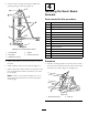
Form No. 3369-710 Rev B Sonic Boom™ Kit 2010 and After Multi-Pro® Turf Sprayers and Workman® 200 Spray System Model No. 41218—Serial No. 311000001 and Up Installation Instructions This attachment maintains consistent distances from the boom nozzles to the ground when spraying over uneven surfaces and is intended to be used by professional, hired operators in commercial applications. It is primarily designed for spraying golf course applications, parks, sports fields, and on commercial grounds.
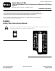
Installation Loose Parts Use the chart below to verify that all parts have been shipped. Procedure 1 2 3 4 5 Description Qty. Use No parts required – Prepare the machine. No parts required – Remove the hardstops.
Procedure 6 7 8 Description Use Qty. Decal, 94-8582 Light assembly Rocker switch Cable ties Indicator light (Workman 200 only) Grommet (Workman 200 only) 1 1 1 6 1 1 No parts required – Install the indicator light. Install the controls. Calibrate the sonic booms. Note: Decal 119-9431 is used with a hand-held diagnostic tool and therefore is not installed on the machine. Note: Determine the left and right sides of the machine from the normal operating position. 1.
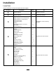
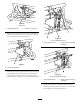
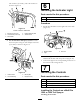
3 3 Assembling the Sensor Mounting Hardware Parts needed for this procedure: 2 Hinge 2 Angled strap (for an uncovered boom) 2 Angled strap (for a covered boom) 2 Top or bottom strap 4 Compression spring 8 Bushing 4 Hex-head bolt (5/16 x 3-1/4 inch) 12 Flat washer 4 Locknut (5/16 inch) 1 2 G017128 3 Figure 2 For uncovered booms only 1. Hinge (2) 3. Bushings (8) 2. Angled strap (2) 4.
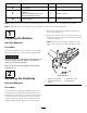
4. Insert the bolts through the hinged welded tube openings, hinges, and straps (Figure 4). 4 Installing the Sonic Boom Sensors Parts needed for this procedure: Figure 4 Hardware for a covered boom shown 1. Hex-head bolt 4. Springs 2. Flat washer 5. Locknuts (5/16 inch) 3.
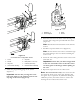
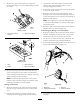
2 G017148 1 Figure 6 Rear view 1. Mounting bracket (2) G017150 2. Locknuts (1/4 inch) (12) 2. Install the sensor guard bracket onto the mounting bracket with 2 bolts (5/16 x 3/4 inch) and 2 flange nuts (5/16 inch) as shown in Figure 7. 2 1 Figure 8 For a covered boom only 1. Sensor guard bracket 2. Hinge (of sensor mounting hardware) G017149 1 Figure 7 1. Sensor guard bracket G017157 3.
1 2 6 3 4 3 5 Figure 11 7 8 1. Sideways “T” 3. Notch 2. Arrows aligned 4. Sensor 6. Insert the sensor into the lower sensor housing, and secure it with 2 large nuts provided with the sensor (Figure 10). Note: Discard the lock washers that come with the sensors. 7. Install the cap tube and the cover (Figure 10). Note: Ensure that the sensor wire is routed through the small opening in the cover before installing the sensor cover. G017151 Figure 10 Uncovered boom configuration shown 1. Cover 5.
5 2 1 Mounting the Electronic Control 3 4 5 8 Parts needed for this procedure: 1 Mount plate 4 Relay 4 Bolt (1/4 x 5/8 inch) 4 Lock washer (1/4 inch) 4 Nut (1/4 inch) 2. Nut (1/4 inch) 6. Nut (#10) 1 Wire harness 3. Lock washer (1/4 inch) 7. Screw (#10) 4 Screw (#10) 4. Bolt (1/4 x 5/8 inch) 8.
lock washers (5/16 inch), and 2 flat washers as shown in Figure 14. 4 3 6 5 Installing the Indicator Light 2 1 Parts needed for this procedure: 1 Decal, 94-8582 1 Light assembly Procedure 1. Install decal 94-8582 over the light hole in the dash (Figure 16). G016082 Figure 14 Frame under the dashboard 2 1. Bolt (5/16 x 3/4 inch) 4. ECM and Mount plate 2. Lock washer (5/16 inch) 5. Vehicle frame 1 3. Flat washer B.
1. Remove the spray control panel to expose the bottom side (Figure 17 for the 1200 and Figure 18 for the 1250). 3. Connect the connectors labeled “left boom lift switch” and “right boom lift switch” to the corresponding panel switches. 4. Connect the connector labeled “sonic boom switch” to the sonic boom switch. 5. Route the free end of the wiring harness down through the floor and rearward, following the spray system wire harness to the center boom assembly at the back of the vehicle.
Note: The load side can be determined by testing both solenoid posts when the ignition is turned off. The hot side will read approximately 12V, while the load side will have no voltage. The load side can be confirmed by turning the ignition to the Run or On position and testing the load side again. The load side will read approximately 12V with the ignition on. Turn the ignition to Off and remove the key before continuing with any of the installation or maintenance. 5. Lower the seat.
6. Connect the connector labeled “sonic boom switch” to the sonic boom switch. 7. Connect the light indicator to the wiring harness with two spade connectors. 8. Install the front control panel cover to the control box using the fasteners that you removed previously (Figure 20). 9. Route the remainder of the harness rearward, along the existing sprayer harness to rear of the machine. 10. Secure the harnesses with cable ties. Connecting the Wiring to the Fuse Block 1.
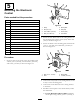
Note: Replace the cover if necessary. Note: Tie back any loose wiring to protect it from being damaged. 8 Calibrating the Sonic Booms No Parts Required Procedure Figure 24 In this procedure, you will have 20 seconds to calibrate the sensors on the booms. The distance you set between the sensor on each boom and the ground after the 20-second calibration period is the boom height setting in automatic mode until the next time you calibrate the sensor.
Operation Using the Controls • On momentarily: The light comes on when you activate the sonic boom system. The light will turn off after a few seconds and remain off as long as the system is operating properly. The Sonic boom switch is located on the dashboard and has 2 settings: Automatic and Manual. • Flashing: There is an active fault in the sonic boom system.
Maintenance Cleaning Clean the sensors periodically with a damp cloth. If a sensor is damaged or excessively dirty, replace it. Important: Do not spray water at or on the sensors. Water sprayed under even household pressure can damage the sensor. Always cover the sensors completely before washing the sprayer. Note: When the booms are in the cradle for extended periods of time, the seal around each sensor (which is oriented upward) may get exposed to ultraviolet light and gradually deteriorate.
Troubleshooting Note: Refer to the service manual for additional diagnostic information. Problem One or both booms malfunction; the sonic boom light is Off. One or both booms malfunction; the sonic boom light flashes slowly. One or both booms are malfunctioning; the sonic boom light is on. Possible Cause Corrective Action 1. A fuse is blown. 1. Replace the fuse. 2. The light is burned out. 3. The electronic controller or wiring is damaged. 2. Replace the light. 3.
Schematics G016373 Electrical (Rev.
Notes: 18
Notes: 19