
Installation Instructions
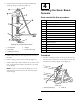
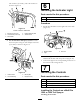

1.Removethespraycontrolpaneltoexposethe
bottomside(Figure17forthe1200andFigure18for
the1250).
Figure17
MultiPro1200
1.Sonicboomswitch
location
2.Spraycontrolpanel
Figure18
MultiPro1250
1.Plug
3.Notch(atback)
2.Switch4.Spraycontrolpanel
2.Removethepluginthesonicboomslotfromthe
spraycontrolpanelonthevehicle,andinstallthe
rockerswitchprovidedinitsplace(
Figure17forthe
1200andFigure18forthe1250).
Note:Ensurethattheorientationoftheswitch
matcheswhatisshowninFigure18,withthenotch
pointingtowardtherearofthevehicle.
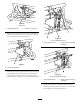
WiringtheSwitches
1.Routethebranchofthesonicboomwireharness
withthe3largeconnectorsintothecontrolpanel
area.
2.Ifboomliftswitchesareinstalled,removeany
existingconnectorspluggedintotheliftswitches.
3.Connecttheconnectorslabeled“leftboomlift
switch”and“rightboomliftswitch”tothe
correspondingpanelswitches.
4.Connecttheconnectorlabeled“sonicboomswitch”
tothesonicboomswitch.
5.Routethefreeendofthewiringharnessdown
throughtheoorandrearward,followingthespray
systemwireharnesstothecenterboomassemblyat
thebackofthevehicle.
Note:Usecabletiestosecurethewiringharness
totheotherwiringharnessesawayfromtheengine
andmovingparts.
6.Installthespraycontrolpanelandsecureitwiththe
fastenersthatyouremovedpreviously.
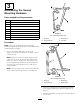
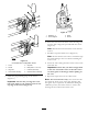
ConnectingtheWiringtotheFuseBlock
1.Routethebranchofthesonicboomwiringharness
withthesmallspadeconnectorandaringorfork
terminalintotheseatboxandtothefusearea.
2.Lifttheseattoaccessthefusearea,andlocatethe
auxiliarysolenoidandgroundterminalblock.
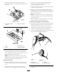
3.Connecttheringlabeledgroundontheblackwireto
thegroundterminalblock(
Figure19).
Figure19
1.Blackwire3.Redwire
2.Groundterminalblock
4.Auxiliarysolenoid
4.Connecttheredwiretotheloadsideoftheauxiliary
solenoid.
10