
Installation Instructions

1
2
4
3
3
5
G017151
6
7
8
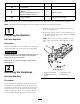
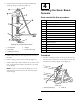
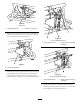
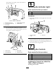
Figure10
Uncoveredboomcongurationshown
1.Cover5.Captube
2.Sensor6.Bolts(5/16x1-1/4inch)
3.Largenut
7.Locknuts(5/16inch)
4.Lowersensorhousing8.Finishedsensorassembly
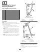
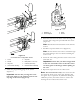
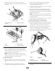
5.Installtheprogrammingplugonthesensor
(Figure11).
Important:Ensurethatyoualignthearrow
belowthesideways“T”withthenotchonthe
topedgeofthesensor(Figure11).
Figure11
1.Sideways“T”
3.Notch
2.Arrowsaligned
4.Sensor
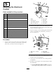
6.Insertthesensorintothelowersensorhousing,and
secureitwith2largenutsprovidedwiththesensor
(Figure10).
Note:Discardthelockwashersthatcomewiththe
sensors.
7.Installthecaptubeandthecover(Figure10).
Note:Ensurethatthesensorwireisroutedthrough
thesmallopeninginthecoverbeforeinstallingthe
sensorcover.
8.Securethewirecomingfromthesensortotheboom
withcableties.
Important:Ensurethatyouallowenoughslack
inthewirearoundthesensorsothatthesensor
canfreelypivotonthehingewithoutpullingon
thewire.
9.Repeatthestepsabovefortheotherboom.
Note:Forcoveredboomsonly:Thesensorsshould
notdetecttheboomcoverasthismayinterferewith
thesignal.Ifyouexperienceanydifcultiesduringthe
calibrationprocess,checkthesensorstoensurethat
theirsignalsdonotdetecttheboomcover.
7