
Installation Instructions

5
MountingtheElectronic
Control
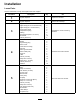
Partsneededforthisprocedure:
1Mountplate
4Relay
4
Bolt(1/4x5/8inch)
4
Lockwasher(1/4inch)
4
Nut(1/4inch)
1Wireharness
4
Screw(#10)
4
Nut(#10)
1
ElectronicControlUnit(ECU)
4
Bolt(1/4x1-1/4inch)
4
Locknut(1/4inch)
2
Bolt(5/16x3/4inch)
2
Lockwasher(5/16inch)
2Flatwashers
2U-boltclamps
4
Nut(5/16inch)
Procedure
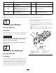
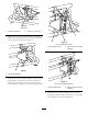
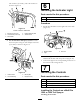
1.Secure4relaystothefrontofthemountplatewith
4bolts(1/4x5/8inch),4lockwashers(1/4inch),
and4nuts(1/4inch)asshownin
Figure12.
G016281
1
2
3
4
5
6
7
8
Figure12
1.Relay5.Mountplate
2.Nut(1/4inch)6.Nut(#10)
3.Lockwasher(1/4inch)7.Screw(#10)
4.Bolt(1/4x5/8inch)
8.Fuseblock
2.Securethefuseblockendsofthewiringharnessto
themountingplatewith4screws(#10)and4nuts
(#10)asshowninFigure12.
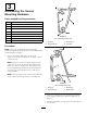
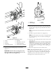
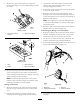
3.SecuretheECUtothemountingplatewith4bolts
(1/4x1-1/4inch)and4locknuts(1/4inch)as
shownin
Figure13.
G016081
1
2
3
4
Figure13
1.Bolt(1/4x1-1/4inch)
3.Mountplate
2.ECU4.Locknut(1/4inch)
4.Connecttherelayleadsonthewiringharnesstothe
4relaysonthemountingplate.
5.Connectthecontrollerleadonthewiringharness
totheECU.
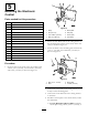
6.Installthemountplatetothevehicleframe,under
thedashboard.
A.FortheMulti-Pro1200and1250:Installthe
mountplateusing2bolts(5/16x3/4inch),2
8