
Installation Instructions


1
®
FORM NO. 92-3714
MODEL NO. 41224-90001& UP
SET-UP AND
PARTS LIST
FOAM MARKER KIT
for the WORKMAN
SPRAY SYSTEM
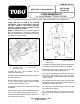
Refer to the illustrated Parts List for the details of parts used in assembling the Foam Marker Kit.
FIG. 1
1. Foam Marker Decal 3. Wire Harness
2. Foam Marker Switch
NOTE: If installing this Kit on a vehicle equipped
with "Enclosed Boom," work these instructions
with the "Enclosed Boom" Instructions found in
the Set-up and Parts manual.
"Right" and "Left" as used in the following
instructions, refer to the operator's right and
left when seated in the normal operating
position. Likewise, "Front" and "Rear" as seen
from the operator's position.
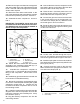
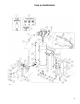
FIG. 2
1. Tank Ass'y 3. Plastic Check Valve
2. Tank Bracket
©The TORO Company - 1999
All Rights Reserved
1. Install the Toro Spray System as per
instructions with that kit.
2. Raise the tank and skid assembly and support
with the support rod.
3. Remove the (4) 3/8" x 1" hex hd cap screws and
(2) nuts securing the radiator cover to vehicle
frame and remove radiator cover.
4. Unplug the wire harness connectors from both
headlights.
5. Remove the (15) screws and washers securing
front hood to vehicle frame and remove hood.
6. Affix foam marker decal around the right hole of
the switch bracket (FIG. 1).
7. Mount foam marker switch in the lower right hole
of the switch bracket with (2) hex nuts. See FIG. 1.
8. Plug the (2) push-on terminals of the wire
harness into foam marker switch (FIG. 1).
9. Route the wiring harness under the dash panel
and secure with cable ties to the front frame
support. Harness must not interfere with operation
of any controls.
10. Route harness through opening in floorboard
following the electric clutch wiring harness towards
the rear of the passenger seat.
11. Affix foam marker 20 amp fuse decal to any
unused circuit on vehicle.
12. Plug the 6" lead of the foam marker wire
harness into the fuse block lead wire as chosen in
Step 11.
1498
1499