Form No. 3353-750 Rev C Foam Marker Kit for Multi-Pro 1200, 1250, 5600 and 5700 Turf Sprayers and Workman 200 Spray Systems Model No. 41228—Serial No. 260000001 and Up Installation Instructions Note: Determine the left and right sides of the machine from the normal operating position. Note: If you are installing this kit on a machine equipped with an enclosed boom system, use these instructions along with the enclosed boom system instructions.
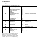
Installation Loose Parts Use the chart below to verify that all parts have been shipped. Procedure 1 2 3 4 5 Description Qty.
1 Installing the Tank, Compressor, and Mixer Parts needed for this procedure: 1 Tank/compressor assembly 2 Supply hose, 108 inches 1 Multi-Pro 1200 series adapter bracket 1 Workman adapter bracket 1 Mud flap 1. Battery 1 Mud flap bracket 4 Bolt (3/8 x 1 inch) 2.
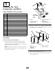
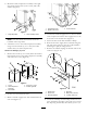
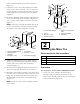
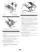
Multi Pro 5600/5700 Turf Sprayer 1. Remove 4 bolts (1/4 x 1 inch) and flat washers that hold the cover to the tank/compressor assembly (Figure 5). Figure 3 1. Compressor hose 2. Needle valve hose 3. To the mixer tee 5. Connect the marked supply hose to the hose barb at the compressor and the other supply hose to the hose barb on the needle valve (Figure 3). Figure 5 1. Cover 2. Tank/compressor assembly 3. Flat washer 6. Secure the hose ends with small hose clamps. 7.
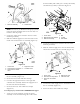
8. Mount the tank/compressor assembly to the right step frame using 2 bolts (3/8 x 1 inch) and 2 flat washers (Figure 7). Figure 9 1. Compressor hose 2. Needle valve hose 3. To the mixer tee Figure 7 1. Right step frame 4. Connect the marked supply hose to the hose barb at the compressor and the other supply hose to the hose barb on the needle valve (Figure 9). 5. Secure the hose ends with small hose clamps. 6.
inch) and three locknuts (5/16 inch) as shown in Figure 10. 9. Attach the cover to the tank/compressor assembly using 3 of the 4 hex-head bolts (1/4 x 1 inch) and flat washers that you removed previously. Leave the bottom right bolt out until later in the installation (Figure 8). 10. Mount the Workman adapter bracket supplied in the kit to the tank/compressor assembly using 2 bolts (3/8 x 1 inch), 2 flat washers (3/8 inch) as shown Figure 11.
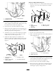
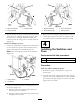
boom assembly with a bolt (3/8 x 1 inch), flat washer, and locknut (3/8 inch) as shown in Figure 15. Figure 13 1. Mixer tee assembly 2. Center boom Note: If necessary on Workman 200 Spray Systems, rotate the mixer assembly down so that it does not interfere with the pump. 2. Locate the supply hoses routed to the rear of the machine previously. 3. Slide the marked supply hose onto the barb on the check valve located at the tee assembly (Figure 14). Figure 15 4. Bolt 1. Center boom 2.
6. Connect the right boom hose to the right side solenoid valve assembly and the left supply hose to the left side solenoid assembly. 7. Secure both hoses with small hose clamps (Figure 16). 3 Wiring the Kit Parts needed for this procedure: 1 Wiring harness 6 Hose clamp, small 12 Plastic ties Figure 18 1. Mixer tee assembly 2. Boom solenoids 3. Wiring harness Multi Pro 5600/5700 Turf Sprayer 1.
Figure 22 Figure 20 1. Mixer tee assembly 2. Boom solenoids 1. Mixer tee assembly 2. Boom solenoid, right 3. Wiring harness 3. Plug the harness connectors into the boom solenoids at the mixer tee assembly. Plug the connector with the blue wire to the right solenoid and plug the connector with the orange wire to the left solenoid (Figure 20). 3. Boom solenoid, left 4. Wiring harness 3. Route the hoses along the wiring harness to the rear of the sprayer and to the mixer tee using the cable ties.
Figure 25 Figure 23 1250 1. Plug 2. Switch 1. Control panel 2. Latch 3. Notch (at back) 4. Spray control panel 3. Foam marker switches 3. Remove the foam marker switch hole plugs. 4. Install the 2 rocker switches into the switch panel. Note: Ensure that the notch/hole on the bottom of each switch is oriented toward the rear of the vehicle. 5. Plug the harness connectors found in the center console into the foam marker switches. Note: The plugs in the harness are marked: Boom foam RS/LS switch.
5 Completing the Installation Parts needed for this procedure: Figure 26 1. Screw 2. Front panel 3. Control box 4. Plug 5. Rocker Switch 6. Connectors 3. Lift and remove the 2 plugs from the spray control panel on the vehicle and install the 2 rocker switches provided in their place (Figure 26). 2 Boom hose 2 Grommet 2 Punched-hole boom cap 2 Extension hose 2 Hose clamp, large 1 Parts catalog Procedure For all sprayers, serial number 259999999 and lower 4.
Note: This allows you to install the boom hoses more easily. 14. Secure all loose wires and hoses to the vehicle frame using plastic ties. 5. Remove the existing boom cap from the end of the boom pipe. 15. Close the foam density adjustment valve completely (Figure 33). 6. Insert the boom hose into the hole drilled in the right boom pipe and push it into the boom pipe until the hose appears at the end of the boom pipe.
For all sprayers, serial number 260000001 and higher 1. Install a grommet over the boom hose coming from the left side of the mixer tee. 2. Route the hose from mixing tee through the cut-out on the underside of the top bar in the boom frame (Figure 30). Feed the hose until the it extends 2-3 inches beyond the end of the frame tube. Figure 31 1. Top bar, boom frame 2. Boom hose 3. Cap 4. Hose clamp 5. Extension hose 6. Assembled 5.
Operation Using the Controls Right boom switch—activates the compressor, generating a flow of foam to the right boom section. Left boom switch—activates the compressor, generating a flow of foam to the left boom section. Figure 32 Note: You can drop the foam simultaneously from both boom sections. 1. Pressure relief valve Sight gauge—indicates the solution level in the tank. It is located on the side of the tank. 2. Lid clamp 3.
9. Start operating the marking system and make a test pattern on the ground. When you first start the marking system, allow 1 to 2 minutes for the foam to flow through the line. 10. Adjust the foam density adjustment valve to obtain the desired consistency and spray as normal. Note: If you leave the foam in the line for more than 2 hours, it may become watery. Before operating after a break of 2 or more hours, run the machine for 1 to 2 minutes to remove the excess water.
slow or no foam production, remove and clean the strainer. Storage 1. Position the vehicle on a level surface, set the parking brake, stop the pump, stop the engine, and remove the ignition key.‘ 1. Remove the couplers on top of the tank. 2. Loosen and unhook the foam marker tank strap. 3. Remove the tank from the bracket, remove the tank lid, and empty the contents of the tank. 2. Relieve pressure within tank by flipping the pressure release valve into the upright position (Figure 32). 4.