Form No. 3365-189 Rev A Workman® 200 Spray System Heavy-Duty Workman® Vehicles Model No. 41235—Serial No. 310000001 and Up G011763 The installation of the Workman® 200 Spray System requires the installation of one or more interdependent kits. Contact your Authorized Toro Dealer for more information. To register your product or download an Operator's Manual or Parts Catalog at no charge, go to www.Toro.com.
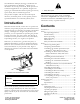
The Workman® 200 Spray System is a dedicated turf spray modification for Workman® vehicles and is intended to be used by professional, hired operators in commercial applications. It is primarily designed for spraying on well-maintained lawns in parks, golf courses, sports fields, and on commercial grounds. Figure 2 1. Safety alert symbol. This product complies with all relevant European directives, for details please see the separate product specific Declaration of Conformity (DOC) sheet.
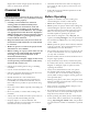
Safety Spraying Tips ..................................................... 33 Cleaning the Sprayer ........................................... 33 Calibrating the Spray Pro Monitor....................... 35 Calibrating the Boom Bypass Valves.................... 37 Pump ................................................................. 37 Maintenance............................................................... 39 Recommended Maintenance Schedule(s) ................ 39 Daily Maintenance Checklist............
High Lockout switch if high speed could result in a safety or vehicle abuse situation. • Chemicals and fumes in the tanks are dangerous; never enter the tank or place your head over or in the opening. • Follow all local/state/federal requirements for the spraying of chemicals. Chemical Safety WARNING Before Operating Chemical substances used in the spray system may be hazardous and toxic to you, bystanders, animals, plants, soils or other property.
• Since gasoline is highly flammable, handle it carefully. – Use an approved gasoline container. – Do not remove the cap from the fuel tank when the engine is hot or running. – Do not smoke while handling gasoline. – Fill the fuel tank outdoors, and fill it to about 1 inch (25 mm) below the top of the tank (the bottom of the filler neck). Do not overfill it. – Wipe up any spilled gasoline. • Use only an approved non-metal, portable fuel container.
• If the engine stalls or you begin to lose headway while climbing a hill, gradually apply the brakes and slowly back straight down the hill. • Turning while traveling up or down hills can be dangerous. If you have to turn while on a hill, do it slowly and cautiously. Never make sharp or fast turns. • Heavy loads affect stability. Reduce the weight of the load and your speed when operating on hills. • Avoid stopping on hills, especially with a load.
• Never work under a sprayer without using tank support prop rod. • Make sure all hydraulic line connectors are tight, and all hydraulic hoses and lines are in good condition before applying pressure to the system. • Keep body and hands away from pin hole leaks that can eject hydraulic fluid under high pressure. Use paper or cardboard, not hands, to search for leaks. any inquiries to The Toro® Company, Commercial Division, Vehicle Engineering Dept., 300 West 82nd St., Bloomington, Minnesota 55420–1196.
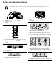
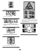
Safety and Instructional Decals Safety decals and instructions are easily visible to the operator and are located near any area of potential danger. Replace any decal that is damaged or lost. 106-5065 107-8621 1. Agitation on 2. Continuous variable setting 1. On 2. Tank drain 3. Agitation off 3. Off 106-5016 1. Warning—read the Operator’s Manual. 2. Electric shock hazard, overhead power lines—stay away from overhead power lines. 3. Crushing hazard, boom—keep bystanders a safe distance from the machine.
106-1354 1. 540 RPM 106-1355 1. Warning—do not enter the tank. 119-0651 1. Tipping hazard, loss of control—do not raise the tank when filled; do not drive the vehicle while tank is raised. Raise the tank when empty only; always lower the tank completely before driving the vehicle. 106-1365 1. Crushing hazard, sprayer tank—keep bystanders a safe distance from the sprayer tank and read the Operator’s Manual. 108-3307 106-1434 1.
8-3309 1. 2. 3. 4. 5. 6. 7. Total area Boom select Speed Units of measure Select units Application rate Sub area 8. 9. 10. 11. 12. 13. Width Distance Speed calibration Sub volume Total volume Flowmeter calibration 107-2825 1. 2. 3. 4. Monitor On Off Continuous variable setting, spray pressure 5. Increase 6. 7. 8. 9. Decrease Locked Unlocked Master boom spray 10. Left boom 11. 12. 13. 14. Center boom Right boom Spray on Spray off 15. Automatic 10 16. 17. 18. 19.
Setup Loose Parts Use the chart below to verify that all parts have been shipped. Procedure 1 2 Description Qty. Use No parts required – Remove the existing bed. No parts required – Prepare the Workman®. 3 Cover assembly Gear tooth assembly Screw (M6 x 1 inch x 12) Spring washer (M6) 1 1 1 1 Install the vehicle speed sensor. 4 No parts required – Install the PTO kit.
Procedure 11 12 14 Description Use Qty. 1 10 10 2 4 4 1 1 3 2 2 2 2 1 1 1 1 1 1 Center boom assembly Bolt (3/8 x 1-1/4 inches) Lock nut (3/8 inch) Boom transport cradle Bolt (1/2 x 1-1/4 inches) Flange nut (1/2 inch) Left boom extension Right boom extension Hose clamps R-clamp Shoulder bolt Washer Nut Operator’s Manual Operator Training Material Parts Catalog Registration Card Selection guide Pre-delivery Inspection Sheet Install the boom assembly. Install boom hoses.
3 Installing the Vehicle Speed Sensor (for Workman® 3000, 4000 series only) Parts needed for this procedure: Figure 4 1. Left rear corner of bed 2. Vehicle frame channel 3. Pivot plate 4. Clevis pin 5. Lynch pin 1 Cover assembly 1 Gear tooth assembly 1 Screw (M6 x 1 inch x 12) 1 Spring washer (M6) Procedure This procedure applies to Workman HD series vehicles with a serial number of 289999999 and lower only.
5 Installing the Electrical Harness Parts needed for this procedure: Figure 6 1. Cover 2. Screw (M6 x 1.00 x 12) 3. Spring washer (M6) 4. Geartooth sensor 5. Seal 6. Forward face 4. Install the geartooth sensor using the screw (M6 x 1.00 x 12) and spring washer (M6) as shown in Figure 6. 5. Install the muffler bracket over the new cover assembly.
(#10-24 x 3/4 inch) and two locknuts (#10-24) as shown in Figure 8. 8. Remove any dirt, grease from the existing fuse block decal and make sure the surface is clean and dry. Place the decal 9. Install the fuses and thermal breakers: A. Install the two 30 amp thermal breakers to the left and right boom lift fuse slots (Figure 8). B. Install the 10 amp fuse to the spray system power fuse slot (Figure 8). 10.
Figure 11 1. 2. 3. 4. 5. Wire harness New fuse block Yellow wire Orange wire Red wire 7. 8. 9. 10. 11. Black ground wire Foam marker fuse slot Left boom actuator slot Right boom actuator slot Spray system power fuse slot 6. Pink wire Figure 10 8. Connect the black ground wire to the existing 1/4 inch bolt on the interior side of the vehicle frame, using the star washer (Figure 12). 1. Hood 2.
2 11. Locate a suitable location near the fuse box to install the fuse decal. Make sure the surface is clean and dry, then place the decal G012932 3 12. Install the fuses and thermal breakers: A. Install the two 30 amp thermal breakers to the left and right boom lift fuse slots (Figure 12). B. Install the 10 amp fuse to the spray system power fuse slot (Figure 12). 13. Route the wiring harness through the opening in the floor, under the seat base, and rearward along with the existing wiring. 1 14.
For vehicles with a serial number of 239999999 or lower 6 Installing the Adapter Plate Installing the Control Box Mount If you are installing the spray system on a Workman vehicle with a serial number of 239999999 or lower, you will need to use the adapter plate, bolts, and nuts included in the loose parts.
1 2 8 Installing the Radiator Cover (for Workman® 3000, 4000 series only) Parts needed for this procedure: 4 3 G011748 Figure 17 Left hand side shown 1. Lock nut 2. Bolts 1 Radiator cover assembly 4 Bolt (1/4 x 3/4 inch) Procedure 3. Lift cylinder 4. Cotter pin The radiator cover is shipped with an additional panel installed for air cooled vehicles. If you are installing the cover onto a liquid cooled vehicle, remove the extra cover. 2.
3 9 4 2 1 Installing the Tank Skid 5 Parts needed for this procedure: 1 Tank and skid assembly 2 Clevis pins 4 Lynch pins 2 Bolt (1/2 x 1-1/2 inches) 4 Washers (1/2 inch) 2 Nuts (1/2 inch) G011759 Figure 20 1. Support straps 2. Lift cylinders 3. Tank skid brackets Procedure DANGER 4. Clevis pin 5. Lynch pin 5. Use the clevis pin and lynch pin to secure the tank skid to the lift cylinders on both sides of the vehicle. The sprayer tank assembly represents a stored energy hazard.
Important: Verify the PTO shaft is secured by making sure the locking balls are seated in the groove of the output shaft. 10. Check the alignment of the tank skid and the vehicle frame. If necessary, loosen the bolts securing the pivot lug to the tank skid frame slightly (Figure 21). Raise the tank assembly just enough above the vehicle frame to be aligned and lowered into proper position. Tighten the bolts on the pivot lug once the tank skid is aligned with the vehicle frame. 14.
2. Install the control box, with the controls facing the driver, to the control mount using the clevis pin and hair pin removed previously. 1 2 3. Install the hand knob to stabilize the control box. Tighten by hand. 4. Install the Spray Pro Decal to the monitor (Figure 25). G011762 Figure 27 1. Drill hole (1/4 inch) 2. 20 inches 8. Secure the control box harness to the console and ROPS cover using the J-clips. 11 Figure 25 1. Spray pro monitor 2. Decal, Upper half 3.
5. Power on the system and use the boom lift switches to extend the boom actuator rods. This is to allow the left and right boom extensions to be installed. 1 6. Remove the four bolts, four washers and four nuts on the hinge plate. 7. Install the extension boom to the center boom at the hinge plate using four bolts, four washers and four nuts removed in step 6 as shown in Figure 30. 2 Note: Ensure all spray turrets are facing to the rear. 3 4 3 4 G012925 Figure 28 1. Boom transport cradle 2.
12 Installing Boom Hoses Parts needed for this procedure: 3 Hose clamps 2 R-clamp 2 Shoulder bolt 2 Washer 2 Nut Procedure 1. Route the boom hoses as shown in Figure 31. 4 5 6 7 1 3 2 G012928 Figure 31 1. Boom hose, left extension 2. Boom hose, center 3. Boom hose, right extension 4. Nut 5. Washer 6. R-clamp 7. Shoulder bolt 2. Use the R-clamps to secure the right and left boom hoses to the front side of the center boom assemblies.
3. Use liquid soap to coat the hose barb of the tee connections on both extension booms (Figure 32). Install the boom extension hose over the barb and secure it with a clamp. 3 1 obtain the correct nozzles for your needs, contact your Authorized Toro Distributor and be prepared to give them then following information: • The recommended application rate in US gallons per acre, US gallons per 1000 sq ft, or liters per hectare. 2 • The target speed or the vehicle in miles per hour or kilometers per hour.
Product Overview Figure 33 1. Power switch, Spray Pro™ monitor 2. Spray Pro™ monitor 3. Application rate switch 4. Rate lockout key switch 7. Center boom switch 5. Master boom switch 6. Left boom switch 8. Right boom switch 9. Left boom lift switch 10. Right boom lift switch Controls Application Rate Switch ™ Monitor Power Switch Spray Pro™ The application rate switch is located on the left side of the control panel (Figure 33).
Sonic Boom and Foam Marker Switch Locations (Optional) Agitation Control Valve This valve is located on the right side of the tank (Figure 35). Turn the knob on the valve to the 9 o’clock position to turn on the tank agitation and to the 3 o’clock position to turn off the tank agitation. If you install the sonic boom and/or the foam marker kit, you will add switches to the control panel for controlling their operation. The sprayer comes with plastic plugs in these locations.
Important: Do not allow the hose receptacle to contact tank fluids. Do not lengthen the hose to allow contact with the tank fluids. Note: The plastic nut on the tank drain should be tightened when not in use to prevent leaks at the drain handle. Figure 36 1. Tank drain handle Tank Cover The tank cover is located in the center of the top of the tank (Figure 37). To open it, turn off the engine and set the parking brake, then turn the front half of the cover to the left and swing it open.
Spray Pro™ Monitor The monitor has an LCD screen that displays the data you select, a selection dial, and 4 buttons for calibrating the monitor (Figure 38). The Spray Pro monitor displays and monitors various system performance data such as vehicle speed and application rates. It does not control the application rate. Figure 38 1. LCD screen 2. Selection dial 3. Total area 4. Speed 5. Units of measure 6. Application rate 7. Distance 8. Sub Area 9. Sub volume 10. Total volume 11.
Specifications setting, without affecting the Total Volume display. If you press the Reset calibration button, the Sub Area resets. Note: Specifications and design are subject to change without notice. • Total Volume Spray system base weight Displays the total volume in US gallons (US and TURF) or liters (SI) that you have applied since you last pressed the Reset calibration button for this setting.
Operation 4. At the hinge, adjust the position of the bumpers so the boom can not move past level with the ground. Take care to make sure the bumper is level. 5. Tighten the bolt and nut to lock the bumpers into the adjusted position. Torque the fasteners to 135-165 ft-lbs (183-223 N-m). Note: Determine the left and right sides of the machine from the normal operating position. Think Safety First Note: The bumper may experience some compression over time.
Filling the Spray Tank Note: Better agitation can be achieved by decreasing the application rate setting. Important: Ensure that the chemicals you will be using are compatible for use with Viton (see the manufacturer’s label; it should indicate if it is not compatible). Using a chemical that is not compatible with Viton will degrade the O-rings in the sprayer, causing leaks.
sure the boom cylinders are fully retracted to prevent actuator rod damage. • Use the master boom switch to stop the spray flow before stopping the sprayer. Once stopped, use the neutral engine speed lock to hold the engine speed up to keep the agitation running. • You will obtain better results if the sprayer is moving when you turn the booms on.
Note: The plastic nut on the tank drain should be tightened when not in use to prevent leaks at the drain handle. 3. Fill the tank with at least 50 US gallons (190 L) of clean fresh water and close the cover. Note: You can use a cleaning/neutralizing agent in the water as needed. On the final rinse, use only clean, clear water. 4. Start the engine. 5. With the shift lever in the Neutral position, engage the PTO, and set the hand throttle. 6. Ensure that the agitation control valve is in the On position. 7.
Calibrating the Spray Pro Monitor Figure 42 1. 2. 3. 4. 5. LCD screen Selection dial Total area Speed Units of measure 6. 7. 8. 9. 10. Application rate Sub Area Distance Sub volume Total volume 11. 12. 13. 14. 15. The Spray Pro monitor has a calibration mode that allows you to change various settings to customize the display and calibrate the monitor to your needs.
1. Stop the sprayer and set the parking brake. 2. Set the master boom switch to the Off position. The monitor displays “HOLD”. 3. Press and hold the Calibrate button until the monitor displays “CAL HOLD” and the red light on the monitor illuminates. 4. Turn the selection dial to the Select Units (or Units of Measure) position. 5. Use the Increase or Decrease calibration buttons to select desired units of measure. 6. Press the Calibrate button until the red light turns off.
for the nozzles you installed on the booms (typically 40 psi). 14. With the selection dial set to the Distance position, press and hold the Calibrate button until the monitor displays “CAL HOLD” and the red light on the monitor illuminates. 10. Record the reading on the pressure gauge. 11. Turn off one of the booms using the appropriate boom switch. The display will alternate between the distance value (“HOLD” shown) and the speed calibration value (“CAL HOLD” shown). 12.
Figure 44 1. Pump 2. Grease fitting 3. Pressure Dampener Adjusting the Air Pressure in Dampener The air pressure in the dampener on the pump is set at 15 psi (1 bar) by the manufacturer. The recommended pressure in the dampener is 1/3 of the spraying pressure. If using a spray pressure greater than 45 psi (3.1 bar) adjust the dampener accordingly.
Maintenance Note: Determine the left and right sides of the machine from the normal operating position. Recommended Maintenance Schedule(s) Maintenance Service Interval Before each use or daily Maintenance Procedure • Clean the suction strainer. (More often when using wettable powders) Every 50 hours • Lubricate the pump. Every 100 hours • Lubricate the grease fittings. • Lubricate the boom hinges. Every 200 hours • Inspect all hoses and connections for damage and proper attachment.
Maintenance Check Item For the week of: Mon. Tues. Wed. Thurs. Fri. Sat. Sun. Clean the suction strainer. Check toe-in. Lubricate all grease fittings.1 Touch up and damaged paint. 1Immediately after every washing, regardless of the interval listed Notation for Areas of Concern Inspection performed by: Item Date Information 1 2 3 4 5 6 7 8 9 10 CAUTION If you leave the key in the ignition switch, someone could accidently start the engine and seriously injure you or other bystanders.
Figure 45 Left side shown 1. Front mounting bracket 2. Hold-down bracket 3. Bolt (1/2 x 1-1/2 inches) 4. Washer (1/2 inch) 5. Locknut (1/2 inch) Figure 47 1. Bed support 2. Cylinder barrel 4. Fold the boom extensions forward, alongside the tank assembly to distribute the weight more evenly and keep it from tipping back. 3. Bed 5. Raise the tank assembly until the lift cylinders are fully extended. Lowering the Tank Assembly 6.
Lubrication Greasing the Boom Hinges Service Interval: Every 100 hours Greasing the Sprayer System Important: If the boom hinge is washed with water, all water and debris must be cleared from the hinge assembly and fresh grease must be applied. Service Interval: Every 50 hours Every 100 hours Grease Type: No. 2 general-purpose lithium base grease. Lubricate all bearings and bushings after every 100 hours or once a year, whichever occurs first. 1.
1 7. With the pin in place, release the boom and secure the pin with the cotter removed previously. 4 2 8. Repeat the procedure for each actuator rod bearing. 5 3 G002016 Figure 50 1. Actuator 2. Actuator rod 3. Boom pivot pin housing 4. Cotter 5. Pin 3. Lift up on the boom and remove the pin (Figure 50). Slowly lower the boom to the hardstop. 4. Inspect the pin for any damage, replace if necessary. 5. Manipulate the actuator rod bearing end and apply grease into the bearing (Figure 51).
Electrical System Maintenance Spray System Maintenance Fuses Inspecting the Hoses The Workman® 200 Spray System adds a fuse block to the vehicles existing electrical system. It is located beneath dashboard with the existing fuse block(s). Service Interval: Every 200 hours Every 400 hours/Yearly (whichever comes first) Examine each hose in the spray system for cracks, leaks or other damage. At the same time, inspect the connections and fittings for similar damage.
Adjusting the Boom Actuator Important: The manual valve must not be loosened more than 4 turns. Turning the valve more than 4 turns may cause the valve to come off completely allowing hydraulic oil to spill out. 1. Locate the manual relief valve on the actuator for each boom. The manual relief valve is the smaller valve and is only on one side of the actuator body (Figure 53). Service Interval: Every 400 hours Inspect the actuator hydraulic oil for air bubbles every 400 hours. 1.
Cleaning 4 Cleaning the Flowmeter 5 Service Interval: Every 200 hours/Yearly (whichever comes first) (More often when using wettable powders) 1. Thoroughly rinse and drain the entire spraying system. 1 2. Remove the flowmeter from the sprayer and flush it with clean water. 2 4 3. Remove the retainer ring on the upstream side (Figure 55). 3 G002017 9 Figure 54 1. Pivot pin 2. Bolt 3. Nut 1 4 5 8 7 4. Nylon bushing 5. Pivot bracket 4.
Storage 1. Position the sprayer on a level surface, set the parking brake, stop the pump, stop the engine, and remove the ignition key. 1. Position the sprayer on a level surface, set the parking brake, disengage the PTO, stop the engine, and remove the ignition key. 2. Remove the retainer from the red fitting attached to the large hose on the top of the tank (Figure 56). 2. Clean dirt and grime from the entire machine, including the outside of the engine’s cylinder head fins and blower housing.
DANGER The sprayer tank assembly represents a stored energy hazard. If not properly retained when installing or removing the assembly it can move or fall and injure you or other bystanders. Use straps and an overhead lift to support the sprayer tank assembly during installation, removal or any maintenance when the retaining fasteners are being removed. 1. Secure and support the sprayer tank assembly with straps to an overhead lift using the eyelets on the skid frame.
Troubleshooting Troubleshooting the Spray System Problem A boom section does not spray. Possible Cause Corrective Action 1. The electrical connection on the boom valve is dirty or disconnected. 1. Turn the valve off manually. Disconnect the electrical connector on the valve and clean all leads, then reconnect it. 2. Blown fuse 2. Check the fuses and replace them as necessary. 3. Repair or replace the hose. 4. Adjust the boom by-pass valves. 3. Pinched hose 4.
Problem The Area is inaccurate. The Distance is inaccurate. The monitor does not display Application Rate or Total Volume. The Total Volume is inaccurate. Possible Cause Corrective Action 1. The sprayer width is not correctly entered. 1. Check and set the appropriate Width in the calibration mode. 2. The speed sensor is not calibrated correctly. 3. The speed sensor is damaged. 2. Calibrate the speed sensor. 1. The speed sensor is not calibrated correctly. 1. Calibrate the speed sensor. 2.
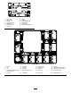
Schematics G011797 Electrical, spray system (Rev.
The Toro Total Coverage Guarantee A Limited Warranty Conditions and Products Covered The Toro® Company and its affiliate, Toro Warranty Company, pursuant to an agreement between them, jointly warrant your Toro Commercial product (“Product”) to be free from defects in materials or workmanship for two years or 1500 operational hours*, whichever occurs first. This warranty is applicable to all products with the exception of Aerators (refer to separate warranty statements for these products).