Form No. 3353-704 Rev C Workman® 200 Spray System For Heavy-Duty Workman Vehicles Model No. 41235—Serial No. 260000001 and Up Register your product at www.Toro.
This manual uses two other words to highlight information. Important calls attention to special mechanical information and Note emphasizes general information worthy of special attention. Introduction Read this manual carefully to learn how to operate and maintain your product properly. The information in this manual can help you and others avoid injury and product damage. Although Toro designs and produces safe products, you are responsible for operating the product properly and safely.
Calibrating the Spray Pro Monitor............................. 36 Calibrating the Boom Bypass Valves................................ 38 Pump ................................................ 39 Maintenance...................................................... 40 Recommended Maintenance Schedule(s) ............................... 40 Daily Maintenance Checklist .............. 41 Notation for Areas of Concern ............................ 41 Premaintenance Procedures.......................
Safety Training Material, Engine Manual, and all labels on the Workman vehicle. Improper use or maintenance by the operator or owner can result in injury. To reduce the potential for injury, comply with these safety instructions and always pay attention to the safety alert symbol, which means CAUTION, WARNING, or DANGER-“personal safety instruction." Failure to comply with the instruction may result in personal injury or death.
• Properly dispose of unused chemicals and chemical containers as instructed by the chemical manufacturer and your local codes. • Chemicals and fumes in the tanks are dangerous; never enter the tank or place your head over or in the opening. • Follow all local/state/federal requirements for the spraying of chemicals. • Be extremely careful when operating around people. Always be aware of where bystanders might be and keep them away from the work area.
use hand holds provided. Keep arms and legs within the vehicle body at all times. Never carry passengers in the box or on attachments. Remember your passenger may not be expecting you to brake or turn and may not be ready. – Do not attempt sharp turns or abrupt maneuvers or other unsafe driving actions that may cause a loss of vehicle control. • Always watch out for and avoid low overhangs such as tree limbs, door jambs, and over-head walkways.
– Remove key from ignition. sprayer must be stopped, avoid sudden speed changes, which may initiate tipping or rolling of the sprayer. Do not slam on the brakes when rolling backward, as this may cause the sprayer to overturn. • Reduce speed and load when operating on rough terrain, uneven ground, and near curbs, holes, and other sudden changes in terrain. Loads may shift, causing the sprayer to become unstable. Note: Block wheels if machine is on an incline.
• Before servicing or making adjustments to the machine, stop the engine, set the parking brake, and remove the key from the ignition to prevent someone from accidentally starting the engine. • Empty the tank before tilting or removing sprayer from vehicle and before storage. • Never work under a sprayer without using tank support prop rod. • Make sure all hydraulic line connectors are tight, and all hydraulic hoses and lines are in good condition before applying pressure to the system.
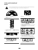
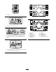
Safety and Instructional Decals Safety decals and instructions are easily visible to the operator and are located near any area of potential danger. Replace any decal that is damaged or lost. 106-5065 107-8621 1. Agitation on 3. 2. Continuous variable setting 1. 2. Agitation off On Tank drain 3. Off 106-5016 1. 2. 3. Warning—read the Operator’s Manual. Electric shock hazard, overhead power lines—stay away from overhead power lines.
6-1354 1. 540 RPM 108-3307 106-1355 1. Warning—do not enter the tank. 108-3309 1. 2. 3. 4. 5. 6. 7. 106-1365 1. Crushing hazard, sprayer tank—keep bystanders a safe distance from the sprayer tank and read the Operator’s Manual. 106-1434 1. Crushing hazard, sprayer tank assembly—read the Operator’s Manual before performing maintenance. 10 Total area Boom select Speed Units of measure Select units Application rate Sub area 8. 9. 10. 11. 12. 13.
107-2825 6. Monitor On 7. Off 8. Continuous variable setting, 9. spray pressure 5. Increase 10. 1. 2. 3. 4. Decrease Locked Unlocked Master boom spray 11. 12. 13. 14. Left boom 15. Automatic 11 Center boom Right boom Spray on Spray off 16. 17. 18. 19. Manual Left boom foam marker Right boom foam marker Lower the boom. 20. Raise the boom.
Setup Loose Parts Use the chart below to verify that all parts have been shipped. Step 1 2 3 4 5 6 7 8 9 Qty. Description Use No parts required – Remove the existing bed. No parts required – Prepare the Workman®.
Step 10 11 12 14 Use Qty.
4. Remove the lynch pins and clevis pins securing the pivot brackets to the frame channels (Figure 4) 2. Turn the engine off and remove the key. 3. Disconnect the negative battery cable from the post. Note: This is a safety precaution since the installation will require installing an electrical harness. Step 3 Installing the Vehicle Speed Sensor Parts needed for this step: 1 1 1 1 Figure 4 1. Left rear corner of bed 2. Vehicle frame channel 3. Pivot plate 4. 5.
Step 3. Install the new cover assembly to the transaxle using the four bolts removed in Step 1 (Figure 6). The correct orientation of the cover will have the seal facing up and positioned toward the left hand side of the vehicle. 4 Installing the Electrical Harness Parts needed for this step: 1 1 2 1 1 2 1 1 8 1 Figure 6 1. Cover 2. Screw (M6 x 1.00 x 12) 3. Spring washer (M6) 4. 5. 6.
8. Remove any dirt, grease from the existing fuse block decal and make sure the surface is clean and dry. Place the decal 9. Install the fuses and thermal breakers: A. Install the 15 amp fuse to the foam marker fuse slot (Figure 8). B. Install the two 30 amp thermal breakers to the left and right boom lift fuse slots (Figure 8). C. Install the 10 amp fuse to the spray system power fuse slot (Figure 8). Figure 7 1. 2. 3. 4. 5. Wire harness New fuse block Yellow wire Orange wire Red wire 7. 8. 9. 10. 11.
Step If you are installing the spray system on a Workman vehicle with a serial number of 239999999 or lower, you will need to use the adapter plate, bolts, and nuts included in the loose parts.
inch) as shown in Figure 12 and Figure 13. Torque the nuts to 30 ± 3 ft-lb (30 ± 4 N⋅m). Figure 14 Figure 12 1. Prop rod 2. Jam nut 3. Yoke Inside view 1. Strut support assembly 3. 2. Left frame rail 4. Socket head bolt (3/8 x 1 inch) Lock nut (3/8 inch) 4. 5. Clevis pin Cotter 6. Bend the cotter pin to secure the prop rod into place. 3. Install the left rear wheel and tire assembly.
Figure 15 Figure 16 Left hand side shown 1. Lift cylinder bracket 2. Hold-down bracket 3. 4. Left hand side shown Bolts Lift cylinder 3. Repeat steps to install the hold-down bracket on the opposite side. 1. Radiator cover assembly 2. Bolt (3/8 x 1 inch) 3. Spray system power connector 3. Secure the cover to the frame using four bolts (3/8 x 1 inch).
1. Using a lift, raise the tank skid assembly and position over the vehicle frame with the pump and valve assemblies facing rearward. 5. Line up the pivot lug at the rear of the tank skid assembly with the opening at the end of the vehicle frame (Figure 19). 2. Turn the prop rod 90° and guide it through the prop rod support (Figure 17) as the tank skid is slowly lowered. Figure 19 Left side shown Figure 17 1. Tank skid assembly 2. Prop rod, turned 90° 3. 1. Pivot lug 2.
Important: Verify the PTO shaft is secured by making sure the locking balls are seated in the groove of the output shaft. 9. Line up the front mounting brackets with the hold down brackets installed previously. 10. Secure the tank skid assembly to the frame with a bolt (1/2 x 1-1/2 inches), two washers (1/2 inch), and a locknut (1/2 inch) as shown in Figure 21. 1. Remove the clevis pin, and hair pin securing the control box to the tank skid. 2.
Step 11 Installing the Boom Assembly Parts needed for this step: 1 10 10 2 4 4 1 1 Figure 23 1. J-clip 2. Existing screws 3. 4. Control box harness Center console 7. Install a J-clip in the ROPS cover behind the operator using a bolt (1/4 x 1 inch) and a nut (1/4 inch). The hole is on the centerline, approximately 20 inches in from the operator’s side edge of the ROPS cover.
shown in Figure 26 with 4 bolts (1/2 x 1-1/4 inches) and four lock nuts (1/2 inch). Note: If necessary, the boom frame mounts can be loosened and adjusted at the center boom assembly for better hole alignment. Figure 27 1. 2. 3. Center boom assembly Boom extension Hinge plate 4. 5. 6. Bolt Washer Nut 8. Repeat step 7 on the other side of the center boom assembly with the opposing boom extension. Figure 26 Note: Ensure all spray turrets are facing to the rear. 4.
Step 12 Installing Boom Hoses Parts needed for this step: 3 2 2 2 2 Hose clamps R-clamp Shoulder bolt Washer Nut Procedure 1. Route the boom hoses as shown in Figure 28. Figure 28 1. 2. 3. Boom hose, left extension Boom hose, center Boom hose, right extension 4. Nut 5. Washer 6. R-clamp 7. Shoulder bolt 2. Use the R-clamps to secure the right and left boom hoses to the front side of the center boom assemblies.
Step 3. Use liquid soap to coat the hose barb of the tee connections on both extension booms (Figure 29). Install the boom extension hose over the barb and secure it with a clamp. 13 Installing the Nozzles No Parts Required Procedure The nozzles you use to apply your chemicals vary depending on the rate of application that you need; therefore, nozzles are not supplied with the kit.
Step 14 Completing the Setup: Learning more about your product. Parts needed for this step: 1 1 1 1 1 1 Operator’s Manual Operator Training Material Parts Catalog Registration Card Selection guide Pre-delivery Inspection Sheet Procedure 1. Read the manuals. 2. View the Operator training material. 3. Use the nozzle selection guide to choose the correct nozzles for your specific application. 4. Store the documentation in a safe place.
Product Overview Figure 30 1. Power switch, Spray Pro™ monitor 2. Spray Pro™ monitor 3. Application rate switch 4. Rate lockout key switch 7. Center boom switch 5. 6. Master boom switch Left boom switch 8. Right boom switch 9. Left boom lift switch Controls 10. Right boom lift switch section on and downward to turn them off. When the switch is turned on, a light on the switch illuminates. These switches will only affect the spray system when the master boom switch is on.
Boom Lift Switches on, you can manually operate each valve by disconnecting the wire connector in the valve, then rotate the knob on the valve clockwise to turn the valve off or counterclockwise to turn it on. The electric boom lift switches raise and lower their respective booms (Figure 30). There is a left and right lift switch. Press and hold the switch upward to raise the respective boom, or press and hold the switch downward to lower the respective boom.
Tank Drain Handle The tank drain handle is located on top of the tank (Figure 33). To open the tank drain, loosen the nut and pull upwards on the T-handle until the desired drain flow is achieved. Important: Pull the handle gently. Do not pull too hard or you may damage the tank drain components. Figure 34 Tighten the plastic nut lock at the base of the handle lock the tank drain in the open position. When the tank has drained, loosen the plastic nut and push the T-handle down until it stops.
Spray Pro™ Monitor The monitor has an LCD screen that displays the data you select, a selection dial, and 4 buttons for calibrating the monitor (Figure 35). The Spray Pro monitor displays and monitors various system performance data such as vehicle speed and application rates. It does not control the application rate. Figure 35 1. 2. 3. 4. 5. LCD screen Selection dial Total area Speed Units of measure 6. 7. 8. 9. 10. Application rate Distance Sub Area Sub volume Total volume 11. 12. 13. 14. 15.
Specications Displays the distance you have traveled in feet (US and TURF) or meters (SI) since you last pressed the Reset calibration button for this setting. Note: Specifications and design are subject to change without notice. Spray system base weight • Sub Volume Tank capacity Displays the total volume in US gallons (US and TURF) or liters (SI) that you have applied since you last pressed the Reset calibration button for this setting, without affecting the Total Volume display.
Operation Note: Determine the left and right sides of the machine from the normal operating position. Chemicals are hazardous and can cause personal injury. Think Safety First • Read the directions on the chemical labels before handling the chemicals and follow all manufacturer recommendations and precautions. Please carefully read all of the safety instructions and decals in the safety section. Knowing this information could help you or bystanders avoid injury. • Keep chemicals away from your skin.
2. Determine the amount of water needed to mix the amount of chemical you need as prescribed by the chemical manufacturer. transport position and spray position without leaving the Operator’s seat. It is recommended to change boom positions while the machine is stationary. 3. Open the tank cover on the spray tank. To change the boom position: The tank cover is located in the center of the top of the tank (Figure 37). To open it, turn the front half of the cover counterclockwise and swing it open.
Spraying Spraying Tips Important: In order to ensure that your solution remains well mixed, use the agitation feature whenever you have solution in the tank. For agitation to work, the PTO must be engaged and the engine must be running above an idle. If you stop the vehicle and need agitation on, place the shift lever in the Neutral position, set the parking brake, Engage the PTO, engage the clutch, and set the hand throttle, if equipped. • Do not overlap areas that you have previously sprayed.
B. Pull up on the T-handle until the desired drain flow is achieved. Important: Pull the handle gently. Do not pull too hard or you may damage the tank drain components. C. Tighten the plastic nut lock at the base of the handle lock the tank drain in the open position. D. When the tank has drained, loosen the plastic nut and push the T-handle down until it stops. E. Tighten the plastic nut to secure the tank drain in the closed position.
Calibrating the Spray Pro Monitor Figure 39 1. 2. 3. 4. 5. LCD screen Selection dial Total area Speed Units of measure 6. 7. 8. 9. 10. Application rate Distance Sub Area Sub volume Total volume 11. 12. 13. 14. 15. The Spray Pro monitor has a calibration mode that allows you to change various settings to customize the display and calibrate the monitor to your needs. You can calibrate or change the following settings: • Boom Width • Units of Measure • Speed • Flowmeter Reset, calibration button 16.
Setting the Units of Measure 8. Compare the volume displayed on the monitor to the volume of water you put into the tank. The default setting for the units of measure is US. You can also change the units to SI (metric) or TURF. 1. Stop the sprayer and set the parking brake. 2. Set the master boom switch to the Off position. The monitor displays “HOLD”. 3. Press and hold the Calibrate button until the monitor displays “CAL HOLD” and the red light on the monitor illuminates. 4.
Note: The boom bypass valves must be calibrated each time the nozzles are changed. 9. Press and hold the Reset calibration button until the display reads “0”. 10. When you reach the start point, press the master boom switch to start the distance tracking with the monitor. Drive the machine from the start point you marked to the 500 ft end point. 11. When you reach the end point, set the master boom switch to the Off position to stop the monitor. 12. Look at the distance displayed on the monitor.
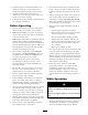
Pump The pump is located near the rear of the vehicle (Figure 41). Figure 41 1. Pump 2. Grease tting 3. Pressure Dampener Adjusting the Air Pressure in Dampener The air pressure in the dampener on the pump is set at 15 psi (1 bar) by the manufacturer. This is recommended for nozzle spray pressures between 20 psi (13 bar) and 45 psi (3 bar). If different nozzle pressures are required, set pressure dampener at pressures indicated.
Maintenance Note: Determine the left and right sides of the machine from the normal operating position. Recommended Maintenance Schedule(s) Maintenance Service Interval Maintenance Procedure Before each use or daily • Clean the suction strainer (more often when using wetable powders). Every 50 hours • Lubricate the pump. Every 100 hours • Lubricate the grease ttings. • Lubricate the boom hinges. Every 200 hours • Inspect all hoses and connections for damage and proper attachment.
Daily Maintenance Checklist Duplicate this page for routine use. Maintenance Check Item For the week of: Mon. Tues. Wed. Thurs. Check the brake and parking brake operation. Check the gear shift/neutral operation. Check the fuel level. Check the engine oil level before lling the tank. Check the transaxle oil level before lling the tank. Inspect the air lter before lling the tank. Inspect the engine cooling ns before lling the tank. Check any unusual engine noises.
If you leave the key in the ignition switch, someone could accidently start the engine and seriously injure you or other bystanders. Remove the key from the ignition and disconnect the wire(s) from the spark plug(s) before you do any maintenance. Set the wire(s) aside so that it does not accidentally contact the spark plug(s). Premaintenance Procedures Lowering the Tank Assembly 1. Raise the tank assembly slightly to disengage the prop rod and carefully lower the tank to the frame.
Lubrication Greasing the Boom Hinges Greasing the Sprayer System Important: If the boom hinge is washed with water, all water and debris must be cleared from the hinge assembly and fresh grease must be applied. Lubricate all bearings and bushings after every 100 hours or once a year, whichever occurs first. Grease Type: No. 2 general-purpose lithium base grease. Grease Type: No. 2 General Purpose Lithium Base Grease 1.
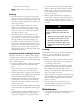
2. Remove the cotter pin from the pivot pin (Figure 44). Figure 45 Right boom 1. Grease bearing 6. Raise the boom to align the pivot with the actuator rod. While holding the boom, insert the pin through both boom pivot and actuator rod (Figure 44). 7. With the pin in place, release the boom and secure the pin with the cotter removed previously. 8. Repeat the procedure for each actuator rod bearing. Figure 44 1. Actuator 2. Actuator rod 3. Boom pivot pin housing 4. 5. Cotter Pin 3.
• Pressure dampener bladder • Pump check valves assemblies Adjusting the manual relief valve with electrical power present could cause the actuator operate irregularly and cause injury to you or others. Replace any components if necessary. Adjusting the Boom Actuator Do not use the manual relief valve while electrical power is being supplied to the actuator. Inspect the actuator hydraulic oil for air bubbles every 400 hours. 2.
cylinder should start stroking manually or by external pressure at this time. 6. Place a small amount of oil on the nylon bushings and install them into pivot bracket. 7. Install the boom and pivot bracket assembly into the center frame, aligning the openings (Figure 47). 8. Install the pivot pin and secure it with the bolt and nut removed previously. 3. Once the original position of the actuator is recovered, close the manual relief valve. Torque the valve to 1.1-2.1 ft-lb (1.5-2.9 N⋅m).
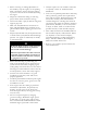
Cleaning the Suction Strainer Clean the suction strainer daily. If you are using wetable powders, clean it after every tank. 1. Remove the retainer from the red fitting attached to the large hose on the top of the tank. Figure 49 1. Suction strainer 2. Disconnect the hose from the tank. 3. Pull the strainer out of the hole. 4. Clean the strainer with clean running water. 5. Replace the strainer, seating it fully into the hole. 6. Connect the hose to the top of the tank and secure it with the retainer.
Storage 13. Store the machine in a clean, dry garage or storage area. 1. Position the sprayer on a level surface, set the parking brake, disengage the PTO, stop the engine, and remove the ignition key. 14. Cover the machine to protect it and keep it clean. Removing the Sprayer 2. Clean dirt and grime from the entire machine, including the outside of the engine’s cylinder head fins and blower housing.
Troubleshooting Troubleshooting the Spray System Problem Possible Cause Corrective Action A boom section does not spray. 1. The electrical connection 1. Turn the valve off on the boom valve is manually. Disconnect dirty or disconnected. the electrical connector on the valve and clean all leads, then reconnect it. 2. Blown fuse 2. Check the fuses and replace them as necessary. 3. Pinched hose 3. Repair or replace the hose. 4. A boom by-pass valve is 4. Adjust the boom by-pass improperly adjusted. valves.
Problem Boom actuator is not operating properly. Possible Cause Corrective Action 1. A thermal breaker in the 1. Wait for the system fuse block responsible for to cool down before powering the actuator resuming operation. has tripped due to If the thermal breaker overheating. trip repeatedly, contact your Authorized Service Dealer. 2. A thermal breaker in 2. Contact your Authorized the boom actuator Service Dealer. responsible for powering the actuator has tripped or malfunctioned.
Problem Possible Cause The monitor does not display Application Rate or Total Volume. 1. The monitor cable is loose. 2. The ow meter is dirty or clogged. 3. The ow meter is not calibrated correctly. 4. The ow meter is damaged. Corrective Action 1. Connect the monitor cable. 2. Clean the ow meter. 3. Calibrate the ow meter. 4. Contact your Authorized Service Dealer. The Total Volume is inaccurate. 1. The ow meter is dirty or 1. Clean the ow meter. clogged. 2. The ow meter is not 2.
Schematics Electrical, spray system (Rev.
The Toro General Commercial Products Warranty A Two-Year Limited Warranty Conditions and Products Covered The Toro Company and its afliate, Toro Warranty Company, pursuant to an agreement between them, jointly warrant your Toro Commercial Product (“Product") to be free from defects in materials or workmanship for two years or 1500 operational hours*, whichever occurs rst.