Form No. 3362-992 Rev A Workman® 200 Spray System for Heavy-Duty Workman Vehicles Model No. 41235—Serial No. 290000301 and Up G011763 The installation of the Workman® 200 Spray System requires the installation of one or more interdependent kits. Contact your Authorized Toro Dealer for more information. To register your product or download an Operator's Manual or Parts Catalog at no charge, go to www.Toro.com.
mechanical information and Note emphasizes general information worthy of special attention. Introduction Contents Read this manual carefully to learn how to operate and maintain your product properly. The information in this manual can help you and others avoid injury and product damage. Although Toro designs and produces safe products, you are responsible for operating the product properly and safely. You may contact Toro directly at www.Toro.
Safety Notation for Areas of Concern ........................... 39 Premaintenance Procedures.................................... 40 Accessing the Machine ....................................... 40 Lubrication............................................................. 41 Greasing the Sprayer System ............................... 41 Greasing the Boom Hinges................................. 42 Greasing the Actuator Rod Bearings ................... 42 Spray System Maintenance...............................
High Lockout switch if high speed could result in a safety or vehicle abuse situation. • Always wash your hands and other exposed areas as soon as possible after finishing the work. • Properly dispose of unused chemicals and chemical containers as instructed by the chemical manufacturer and your local codes. • Chemicals and fumes in the tanks are dangerous; never enter the tank or place your head over or in the opening. • Follow all local/state/federal requirements for the spraying of chemicals.
• Before operating the vehicle, always check all parts of the vehicle and any attachments. If something is wrong, stop using the vehicle. Make sure problem is corrected before vehicle or attachment is operated again. • Since gasoline is highly flammable, handle it carefully. – Use an approved gasoline container. – Do not remove the cap from the fuel tank when the engine is hot or running. – Do not smoke while handling gasoline.
• • • • of the vehicle can produce sparks capable of igniting explosive materials. – If ever unsure about safe operation, stop work and ask your supervisor. Do not use a cab on a Workman vehicle equipped with a spray system. The cab is not pressurized and will not provide adequate ventilation when used with a sprayer. The cab will also overload the vehicle when the spray system tank is full.
• Before servicing or making adjustments to the machine, stop the engine, set the parking brake, and remove the key from the ignition to prevent someone from accidentally starting the engine. • To make sure entire machine is in good condition, keep all nuts, bolts and screws properly tightened. • To reduce potential fire hazard, keep the engine area free of excessive grease, grass, leaves and accumulation of dirt.
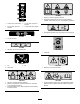
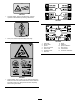
93-0688 1. Warning—read the Operator’s Manual. 2. Caustic liquid/chemical burn and toxic gas inhalation hazards—wear hand, skin, eye, and respiratory protection. 106-1425 1. 15 amp fuse, foam marker 2. 30 amp fuse, left boom actuator 3. 15 amp fuse, right boom actuator 4. 10 amp fuse, spray system 93-7814 1. Entanglement hazard, belt—stay away from moving parts. 93-6687 1. Do not step here. 93-6689 1. Warning—do not carry passengers. 106-1354 1. 540 RPM 106-5065 1. On 2. Tank drain 106-1355 3.
106-1434 1. Crushing hazard, sprayer tank assembly—read the Operator’s Manual before performing maintenance. 108-3307 114-9576 1. Pinch point, hand—keep hand away from hinge. 108-3309 1. 2. 3. 4. 5. 6. 7. 119-0651 1. Tipping hazard, loss of control—do not raise the tank when filled; do not drive the vehicle while tank is raised. Raise the tank when empty only; always lower the tank completely before driving the vehicle.
7-2825 1. 2. 3. 4. Monitor On Off Continuous variable setting, spray pressure 5. Increase 6. 7. 8. 9. Decrease Locked Unlocked Master boom spray 10. Left boom 11. 12. 13. 14. Center boom Right boom Spray on Spray off 15. Automatic 10 16. 17. 18. 19. Manual Left boom foam marker Right boom foam marker Lower the boom. 20. Raise the boom.
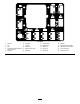
Setup Loose Parts Use the chart below to verify that all parts have been shipped. Procedure 1 2 Description Qty. Use No parts required – Remove the existing bed. No parts required – Prepare the Workman®. 3 Cover assembly Gear tooth assembly Screw (M6 x 1 inch x 12) Spring washer (M6) 1 1 1 1 Install the vehicle speed sensor. 4 No parts required – Install the PTO kit.
Procedure 11 12 14 Description Use Qty. 1 10 10 2 4 4 1 1 3 2 2 2 2 1 1 1 1 1 1 Center boom assembly Bolt (3/8 x 1-1/4 inches) Lock nut (3/8 inch) Boom transport cradle Bolt (1/2 x 1-1/4 inches) Flange nut (1/2 inch) Left boom extension Right boom extension Hose clamps R-clamp Shoulder bolt Washer Nut Operator’s Manual Operator Training Material Parts Catalog Registration Card Selection guide Pre-delivery Inspection Sheet Install the boom assembly. Install boom hoses.
3 Installing the Vehicle Speed Sensor (for Workman® 3000, 4000 series only) Parts needed for this procedure: Figure 4 1. Left rear corner of bed 2. Vehicle frame channel 3. Pivot plate 4. Clevis pin 5. Lynch pin 1 Cover assembly 1 Gear tooth assembly 1 Screw (M6 x 1 inch x 12) 1 Spring washer (M6) Procedure This procedure applies to Workman HD series vehicles with a serial number of 289999999 and lower only.
5 Installing the Electrical Harness Parts needed for this procedure: Figure 6 1. Cover 2. Screw (M6 x 1.00 x 12) 3. Spring washer (M6) 4. Geartooth sensor 5. Seal 6. Forward face 4. Install the geartooth sensor using the screw (M6 x 1.00 x 12) and spring washer (M6) as shown in Figure 6. 5. Install the muffler bracket over the new cover assembly.
4 (#10-24 x 3/4 inch) and two locknuts (#10-24) as shown in Figure 8. 8. Remove any dirt, grease from the existing fuse block decal and make sure the surface is clean and dry. Place the decal 9. Install the fuses and thermal breakers: A. Install the two 30 amp thermal breakers to the left and right boom lift fuse slots (Figure 8). B. Install the 10 amp fuse to the spray system power fuse slot (Figure 8). 10.
2 4 3 8 1 9 10 11 7 6 5 G002492 Figure 11 1. 2. 3. 4. 5. Wire harness New fuse block Yellow wire Orange wire Red wire 7. 8. 9. 10. 11. Black ground wire Foam marker fuse slot Left boom actuator slot Right boom actuator slot Spray system power fuse slot 6. Pink wire Figure 10 8. Connect the black ground wire to the existing 1/4 inch bolt on the interior side of the vehicle frame, using the star washer (Figure 12). 1. Hood 2.
. Use wire ties to secure the harness to the existing wiring and position it away from any moving parts and heat sources. 11. Locate a suitable location near the fuse box to install the fuse decal. Make sure the surface is clean and dry, then place the decal 12. Install the fuses and thermal breakers: A. Install the two 30 amp thermal breakers to the left and right boom lift fuse slots (Figure 12). B. Install the 10 amp fuse to the spray system power fuse slot (Figure 12). 13.
7 Installing the Attachment Hold-down Brackets Parts needed for this procedure: 2 Hold-down brackets Figure 14 1. Control box mount 2. Dashboard Procedure 3. Bolt (5/16 x 1 inch) 4. Lock nut (5/16 inch) 1. Locate and remove the two rear bolts and flange nuts on the lift cylinder bracket (Figure 16). Retain the fasteners for later use.
Figure 17 Left hand side shown 1. Lift cylinder bracket 2. Hold-down bracket Figure 18 Left hand side shown 3. Bolts 4. Lift cylinder 1. Radiator cover assembly 3. Spray system power connector 2. Bolt (3/8 x 1 inch) 4. Repeat steps to install the hold-down bracket on the opposite side. 3. Secure the cover to the frame using four bolts (3/8 x 1 inch).
1. Using a lift, raise the tank skid assembly and position over the vehicle frame with the pump and valve assemblies facing rearward. Note: The following steps are recommended to be performed with the help of another person. 2. Slowly lower the tank skid to the frame. 3. Reconnect the negative battery cable and start the vehicle to energize the hydraulic pumps. 4. Extend the lift cylinders to the brackets on the tank skid. Align the cylinder arms with the holes in the tank skid brackets (Figure 19).
Important: If any hoses or wiring on the tank skid assembly are being pinched or bent, raise the assembly up, adjust its positioning, and tie items back. 12. Repeat on the opposite side. 13. Attach the pump drive: Figure 23 Left side shown 1. Front mounting bracket 2. Hold-down bracket 3. Bolt (1/2 x 1-1/2 inches) 16. Repeat these steps for the front mounting bracket and hold-down bracket on the opposite side. Figure 22 1. Rubber cowling 2. PTO drive shaft 4. Washer (1/2 inch) 5. Locknut (1/2 inch) 3.
1 2 Figure 24 1. Spray pro monitor 2. Decal, Upper half G011762 Figure 26 3. Decal, Lower half 1. Drill hole (1/4 inch) Note: Be sure to orient the decal as shown in Figure 37. 2. 20 inches 8. Secure the control box harness to the console and ROPS cover using the J-clips. 5. Connect the tank skid wiring harness to the spray system power connector. 11 6. Install two J-clips in the center console at the points located in Figure 25 using the existing screws.
5. Power on the system and use the boom lift switches to extend the boom actuator rods. This is to allow the left and right boom extensions to be installed. 1 6. Remove the four bolts, four washers and four nuts on the hinge plate. 7. Install the extension boom to the center boom at the hinge plate using four bolts, four washers and four nuts removed in step 6 as shown in Figure 29. 2 Note: Ensure all spray turrets are facing to the rear. 3 4 G002516 Figure 27 1. Boom transport cradle 2.
12 Installing Boom Hoses Parts needed for this procedure: 3 Hose clamps 2 R-clamp 2 Shoulder bolt 2 Washer 2 Nut Procedure 1. Route the boom hoses as shown in Figure 30. Figure 30 1. Boom hose, left extension 2. Boom hose, center 3. Boom hose, right extension 4. Nut 5. Washer 6. R-clamp 7. Shoulder bolt 2. Use the R-clamps to secure the right and left boom hoses to the front side of the center boom assemblies.
3. Use liquid soap to coat the hose barb of the tee connections on both extension booms (Figure 31). Install the boom extension hose over the barb and secure it with a clamp. therefore, nozzles are not supplied with the kit. To obtain the correct nozzles for your needs, contact your Authorized Toro Distributor and be prepared to give them then following information: • The recommended application rate in US gallons per acre, US gallons per 1000 sq ft, or liters per hectare.
Product Overview Figure 32 1. Power switch, Spray Pro™ monitor 2. Spray Pro™ monitor 3. Application rate switch 4. Rate lockout key switch 7. Center boom switch 5. Master boom switch 6. Left boom switch 8. Right boom switch 9. Left boom lift switch 10. Right boom lift switch Controls Application Rate Switch ™ Monitor Power Switch Spray Pro™ The application rate switch is located on the left side of the control panel (Figure 32).
Sonic Boom and Foam Marker Switch Locations (Optional) Agitation Control Valve This valve is located on the right side of the tank (Figure 34). Turn the knob on the valve to the 9 o’clock position to turn on the tank agitation and to the 3 o’clock position to turn off the tank agitation. If you install the sonic boom and/or the foam marker kit, you will add switches to the control panel for controlling their operation. The sprayer comes with plastic plugs in these locations.
Important: Do not allow the hose receptacle to contact tank fluids. Do not lengthen the hose to allow contact with the tank fluids. Note: The plastic nut on the tank drain should be tightened when not in use to prevent leaks at the drain handle. Figure 35 1. Tank drain handle Tank Cover The tank cover is located in the center of the top of the tank (Figure 36). To open it, turn off the engine and set the parking brake, then turn the front half of the cover to the left and swing it open.
Spray Pro™ Monitor The monitor has an LCD screen that displays the data you select, a selection dial, and 4 buttons for calibrating the monitor (Figure 37). The Spray Pro monitor displays and monitors various system performance data such as vehicle speed and application rates. It does not control the application rate. Figure 37 1. LCD screen 2. Selection dial 3. Total area 4. Speed 5. Units of measure 6. Application rate 7. Distance 8. Sub Area 9. Sub volume 10. Total volume 11.
Specifications setting, without affecting the Total Volume display. If you press the Reset calibration button, the Sub Area resets. Note: Specifications and design are subject to change without notice. • Total Volume Spray system base weight Displays the total volume in US gallons (US and TURF) or liters (SI) that you have applied since you last pressed the Reset calibration button for this setting.
Operation 4. At the hinge, adjust the position of the bumpers so the boom can not move past level with the ground. Take care to make sure the bumper is level. Note: Determine the left and right sides of the machine from the normal operating position. 5. Tighten the bolt and nut to lock the bumpers into the adjusted position. Torque the fasteners to 135-165 ft-lbs (183-223 N-m). Think Safety First Note: The bumper may experience some compression over time.
Important: If you are using a wettable powder, mix the powder with a small amount of water to form a slurry before adding it to the tank As always, remember to clean your sprayer thoroughly after all applications. This will do the most to ensure your sprayer has a long and trouble free life. 8. Add the remaining water to the tank. Filling the Spray Tank Note: Better agitation can be achieved by decreasing the application rate setting.
sure the boom cylinders are fully retracted to prevent actuator rod damage. • Use the master boom switch to stop the spray flow before stopping the sprayer. Once stopped, use the neutral engine speed lock to hold the engine speed up to keep the agitation running. • You will obtain better results if the sprayer is moving when you turn the booms on.
Note: The plastic nut on the tank drain should be tightened when not in use to prevent leaks at the drain handle. 3. Fill the tank with at least 50 US gallons (190 L) of clean fresh water and close the cover. Note: You can use a cleaning/neutralizing agent in the water as needed. On the final rinse, use only clean, clear water. 4. Start the engine. 5. With the shift lever in the Neutral position, engage the PTO, and set the hand throttle. 6. Ensure that the agitation control valve is in the On position. 7.
Calibrating the Spray Pro Monitor Figure 41 1. 2. 3. 4. 5. LCD screen Selection dial Total area Speed Units of measure 6. 7. 8. 9. 10. Application rate Sub Area Distance Sub volume Total volume 11. 12. 13. 14. 15. The Spray Pro monitor has a calibration mode that allows you to change various settings to customize the display and calibrate the monitor to your needs.
1. Stop the sprayer and set the parking brake. 2. Set the master boom switch to the Off position. The monitor displays “HOLD”. 3. Press and hold the Calibrate button until the monitor displays “CAL HOLD” and the red light on the monitor illuminates. 4. Turn the selection dial to the Select Units (or Units of Measure) position. 5. Use the Increase or Decrease calibration buttons to select desired units of measure. 6. Press the Calibrate button until the red light turns off.
14. With the selection dial set to the Distance position, press and hold the Calibrate button until the monitor displays “CAL HOLD” and the red light on the monitor illuminates. 10. Record the reading on the pressure gauge. 11. Turn off one of the booms using the appropriate boom switch. 12. Adjust the boom bypass valve (Figure 42) under the boom control valve for the boom you turned off until the pressure reading on the gauge is the same as it was in step 9.
Maintenance Note: Determine the left and right sides of the machine from the normal operating position. Recommended Maintenance Schedule(s) Maintenance Service Interval Before each use or daily Maintenance Procedure • Clean the suction strainer. (More often when using wettable powders) Every 50 hours • Lubricate the pump. Every 100 hours • Lubricate the grease fittings. • Lubricate the boom hinges. Every 200 hours • Inspect all hoses and connections for damage and proper attachment.
Maintenance Check Item For the week of: Mon. Tues. Wed. Thurs. Fri. Sat. Sun. Clean the suction strainer. Check toe-in. Lubricate all grease fittings.1 Touch up and damaged paint. 1Immediately after every washing, regardless of the interval listed Notation for Areas of Concern Inspection performed by: Item Date Information 1 2 3 4 5 6 7 8 9 10 If you leave the key in the ignition switch, someone could accidently start the engine and seriously injure you or other bystanders.
Premaintenance Procedures 4. Fold the boom extensions forward, alongside the tank assembly to distribute the weight more evenly and keep it from tipping back. 5. Raise the tank assembly until the lift cylinders are fully extended. Accessing the Machine 6. Remove the bed support from the storage brackets on back of the ROPS panel (Figure 45). Rasing the Tank Assembly The sprayer tank assembly represents a stored energy hazard.
Lubrication Do not try to lower the tank assembly with bed safety support on cylinder. Greasing the Sprayer System Service Interval: Every 50 hours 2. Retract the lift cylinders to carefully lower the tank to the frame. Every 100 hours 3. Install the two hold down bolts and fasteners to secure the tank assembly Lubricate all bearings and bushings after every 100 hours or once a year, whichever occurs first. 4. Fold the boom extensions rearward to the extended position. Grease Type: No.
Greasing the Boom Hinges 1 4 2 Service Interval: Every 100 hours 5 Important: If the boom hinge is washed with water, all water and debris must be cleared from the hinge assembly and fresh grease must be applied. Grease Type: No. 2 general-purpose lithium base grease. 3 1. Wipe the grease fittings clean so that foreign matter cannot be forced into the bearing or bushing. 2. Pump grease into the bearing or bushing at each fitting Figure 48. G002016 Figure 49 1. Actuator 2. Actuator rod 3.
Spray System Maintenance 7. With the pin in place, release the boom and secure the pin with the cotter removed previously. 8. Repeat the procedure for each actuator rod bearing. Inspecting the Hoses Service Interval: Every 200 hours Every 400 hours/Yearly (whichever comes first) Examine each hose in the spray system for cracks, leaks or other damage. At the same time, inspect the connections and fittings for similar damage. Replace any hoses and fittings if damaged.
Adjusting the Boom Actuator In case of an emergency such that the boom must be moved and no 12V DC power source is available, the manual relief valve can be used to relieve pressure within the actuator and allow the booms to be moved manually. Service Interval: Every 400 hours Inspect the actuator hydraulic oil for air bubbles every 400 hours. Important: The manual valve must not be loosened more than 4 turns.
2. Extend the booms to the spray position and support the booms using stands or straps from a lift. Cleaning 3. With the weight of the boom supported, remove the bolt and nut securing the pivot pin to the boom assembly (Figure 52). Remove the pivot pin. Cleaning the Flowmeter Service Interval: Every 400 hours/Yearly (whichever comes first) Occasionally, the flowmeter may need to be cleaned to remove an obstruction. 1. Remove the retaining cap from the flowmeter body (Figure 53).
Storage 1. Position the sprayer on a level surface, set the parking brake, disengage the PTO, stop the engine, and remove the ignition key. 2. Clean dirt and grime from the entire machine, including the outside of the engine’s cylinder head fins and blower housing. Important: You can wash the machine with mild detergent and water. Do not use high pressure water to wash the machine. Pressure washing may damage the electrical system or wash away necessary grease at friction points.
The sprayer tank assembly represents a stored energy hazard. If not properly retained when installing or removing the assembly it can move or fall and injure you or other bystanders. Use straps and an overhead lift to support the sprayer tank assembly during installation, removal or any maintenance when the retaining fasteners are being removed. 1. Secure and support the sprayer tank assembly with straps to an overhead lift using the eyelets on the skid frame.
Troubleshooting Troubleshooting the Spray System Problem A boom section does not spray. Possible Cause Corrective Action 1. The electrical connection on the boom valve is dirty or disconnected. 1. Turn the valve off manually. Disconnect the electrical connector on the valve and clean all leads, then reconnect it. 2. Blown fuse 2. Check the fuses and replace them as necessary. 3. Repair or replace the hose. 4. Adjust the boom by-pass valves. 3. Pinched hose 4.
Problem The Area is inaccurate. The Distance is inaccurate. The monitor does not display Application Rate or Total Volume. The Total Volume is inaccurate. Possible Cause Corrective Action 1. The sprayer width is not correctly entered. 1. Check and set the appropriate Width in the calibration mode. 2. The speed sensor is not calibrated correctly. 3. The speed sensor is damaged. 2. Calibrate the speed sensor. 1. The speed sensor is not calibrated correctly. 1. Calibrate the speed sensor. 2.
Schematics G011797 Electrical, spray system (Rev.
Notes: 51
Toro General Commercial Products Warranty A Two-Year Limited Warranty Conditions and Products Covered The Toro Company and its affiliate, Toro Warranty Company, pursuant to an agreement between them, jointly warrant your Toro Commercial Product (“Product”) to be free from defects in materials or workmanship for two years or 1500 operational hours*, whichever occurs first. This warranty is applicable to all products with the exception of Aerators (refer to separate warranty statements for these products).