
Operator's Manual
Important:Ifanyhosesorwiringonthetank
skidassemblyarebeingpinchedorbent,raise
theassemblyup,adjustitspositioning,andtie
itemsback.
12.Repeatontheoppositeside.
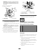
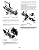
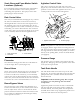
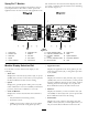
13.Attachthepumpdrive:
Figure22
1.Rubbercowling
3.PTOoutputshaft
2.PTOdriveshaft
•Pullrearwardontherubbercowlingofthefront
ofthePTOdriveshaft(Figure22).
•InstallthedriveshaftontothePTOoutputshaft
(Figure22).
Important:VerifythePTOshaftissecuredby
makingsurethelockingballsareseatedinthe
grooveoftheoutputshaft.
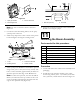
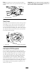
14.Lineupthefrontmountingbracketswiththehold
downbracketsinstalledpreviously.
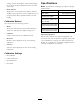
15.Securethetankskidassemblytotheframewitha
bolt(1/2x1-1/2inches),twowashers(1/2inch),
andalocknut(1/2inch)asshowninFigure23.
Figure23
Leftsideshown
1.Frontmountingbracket
4.Washer(1/2inch)
2.Hold-downbracket
5.Locknut(1/2inch)
3.Bolt(1/2x1-1/2inches)
16.Repeatthesestepsforthefrontmountingbracket
andhold-downbracketontheoppositeside.
10
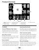
InstallingtheControlBox
Partsneededforthisprocedure:
1Knob
3J-clips
1
Bolt(1/4x3/4inch)
1
Flangenut(1/4inch)
1
SprayProdecal,US
1
SprayProdecal,CE
Procedure
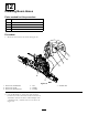
Thecontrolboxismountedonthetankskidbyaclevis
pin,andhairpin.Itislocatedontheleftsidetoward
theback.
1.Removetheclevispin,andhairpinsecuringthe
controlboxtothetankskid.
2.Installthecontrolbox,withthecontrolsfacingthe
driver,tothecontrolmountusingtheclevispinand
hairpinremovedpreviously.
3.Installthehandknobtostabilizethecontrolbox.
Tightenbyhand.
4.InstalltheSprayProDecaltothemonitor
(Figure24).
21