Form No. 3372-914 Rev A Workman® 200 Spray System Heavy-Duty Workman® Vehicles Model No. 41235—Serial No. 312000001 and Up G011763 The installation of the Workman® 200 Spray System requires the installation of one or more interdependent kits. Contact your Authorized Toro Dealer for more information. To register your product or download an Operator's Manual or Parts Catalog at no charge, go to www.Toro.com.
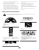
The Workman® 200 Spray System is a dedicated turf spray modification for Workman® vehicles and is intended to be used by professional, hired operators in commercial applications. It is primarily designed for spraying on well-maintained lawns in parks, golf courses, sports fields, and on commercial grounds. Figure 2 1. Safety alert symbol. This product complies with all relevant European directives, for details please see the separate product specific Declaration of Conformity (DOC) sheet.
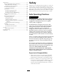
Safety Maintenance .................................................................37 Recommended Maintenance Schedule(s) ......................37 Daily Maintenance Checklist ....................................37 Notation for Areas of Concern.................................38 Premaintenance Procedures ........................................38 Accessing the Machine ............................................38 Lubrication ...............................................................
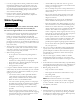
Chemical Safety Before Operating • Operate the machine only after reading and understanding WARNING the contents of this manual. Chemical substances used in the spray system may be hazardous and toxic to you, bystanders, animals, plants, soils or other property. • Carefully read and follow the chemical warning labels and Material Safety Data Sheets (MSDS) for all chemicals used and protect yourself according to the chemical manufacturer's recommendations.
• Use only an approved non-metal, portable fuel container. • Static electric discharge can ignite gasoline vapors in a ungrounded fuel container. Remove the fuel container from the bed of the vehicle and place on the ground away from the vehicle before filling. Keep nozzle in contact with container while filling. Check the safety interlock system daily for proper operation. If a switch should malfunction, replace the switch before operating machine.
• When operating with a heavy load, reduce your speed and • Gross Vehicle Weight (GVW) has a major impact on your allow for sufficient braking distance. Do not suddenly apply the brakes. Use extra caution on slopes. ability to stop and/or turn. Heavy loads and attachments make a vehicle harder to stop or turn. The heavier the load, the longer it takes to stop. • Be aware that heavy loads increase your stopping distance • Turf and pavement are slick when they are wet.
death. Such use could void the product warranty of The Toro® Company. accuracy, have an Authorized TORO Distributor check maximum engine speed with a tachometer. • This vehicle should not be modified without • If major repairs are ever needed or assistance is required, The Toro® Company’s authorization. Direct any inquiries to The Toro® Company, Commercial Division, Vehicle Engineering Dept., 300 West 82nd St., Bloomington, Minnesota 55420–1196. USA contact an Authorized Toro Distributor.
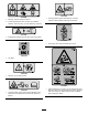
106-1434 93-0688 1. Crushing hazard, sprayer tank assembly—read the Operator's Manual before performing maintenance. 1. Warning—read the Operator's Manual. 2. Caustic liquid/chemical burn and toxic gas inhalation hazards—wear hand, skin, eye, and respiratory protection. 93-7814 1. Entanglement hazard, belt—stay away from moving parts. 114-9576 1. Pinch point, hand—keep hand away from hinge. 106-1354 1. 540 RPM 106-1355 1. Warning—do not enter the tank. 119-0651 1.
108-3309 108-3307 1. Total area 2. Boom select 3. Speed 8. Width 9. Distance 10. Speed calibration 4. Units of measure 5. Select units 6. Application rate 11. Sub volume 12. Total volume 13. Flowmeter calibration 7. Sub area 119-9413 1. Monitor 2. On 6. Decrease 7. Locked 3. Off 8. Unlocked 11. Center boom 12. Right boom 16. Manual 17. Left boom foam marker 13. Spray on 18. Right boom foam marker 4. Continuous variable setting, 9. Master boom spray spray pressure 14. Spray off 19.
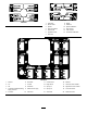
Setup Loose Parts Use the chart below to verify that all parts have been shipped. Procedure 1 2 Description Qty. Use No parts required – Remove the existing bed. No parts required – Prepare the Workman®. 3 Cover assembly Gear tooth assembly Screw (M6 x 1 inch x 12) Spring washer (M6) 1 1 1 1 Install the vehicle speed sensor. 4 No parts required – Install the PTO kit.
Procedure 11 12 14 Description Use Qty. 1 10 10 2 4 4 1 1 3 2 2 2 2 1 1 1 1 1 1 Center boom assembly Bolt (3/8 x 1-1/4 inches) Lock nut (3/8 inch) Boom transport cradle Bolt (1/2 x 1-1/4 inches) Flange nut (1/2 inch) Left boom extension Right boom extension Hose clamps R-clamp Shoulder bolt Washer Nut Operator's Manual Operator Training Material Parts Catalog Registration Card Selection guide Pre-delivery Inspection Sheet Install the boom assembly. Install boom hoses.
3 Installing the Vehicle Speed Sensor (for Workman® 3000, 4000 series only) Parts needed for this procedure: Figure 4 1. Left rear corner of bed 4. Clevis pin 2. Vehicle frame channel 5. Lynch pin 1 Cover assembly 1 Gear tooth assembly 1 Screw (M6 x 1 inch x 12) 1 Spring washer (M6) Procedure 3. Pivot plate This procedure applies to Workman HD series vehicles with a serial number of 289999999 and lower only.
5 Installing the Electrical Harness Parts needed for this procedure: Figure 6 1. Cover 2. Screw (M6 x 1.00 x 12) 4. Geartooth sensor 5. Seal 3. Spring washer (M6) 6. Forward face 5. Install the geartooth sensor using the screw (M6 x 1.00 x 12) and spring washer (M6) as shown in Figure 6. 6. Install the muffler bracket over the new cover assembly.
(#10-24 x 3/4 inch) and two locknuts (#10-24) as shown in Figure 8. 8. Remove any dirt, grease from the existing fuse block decal and make sure the surface is clean and dry. Place the decal 9. Install the fuses and thermal breakers: A. Install the two 30 amp thermal breakers to the left and right boom lift fuse slots (Figure 8). B. 10. Route the wiring harness through the opening in the floor, under the seat base, and rearward along with the existing wiring. Figure 7 1. Wire harness 7.
Figure 11 1. Wire harness 7. Black ground wire 2. New fuse block 3. Yellow wire 4. Orange wire 8. Foam marker fuse slot 9. Left boom actuator slot 10. Right boom actuator slot 5. Red wire 11. Spray system power fuse slot 6. Pink wire Figure 10 1. Hood 8. Connect the black ground wire to the existing 1/4 inch bolt on the interior side of the vehicle frame, using the star washer (Figure 12). 2.
2 11. Locate a suitable location near the fuse box to install the fuse decal. Make sure the surface is clean and dry, then place the decal G012932 12. Install the fuses and thermal breakers: 3 A. Install the two 30 amp thermal breakers to the left and right boom lift fuse slots (Figure 12). B. Install the 10 amp fuse to the spray system power fuse slot (Figure 12). 13. Route the wiring harness through the opening in the floor, under the seat base, and rearward along with the existing wiring. 14.
is mounted. If the hand throttle kit is installed it must be separated from the dashboard in order to install the control mount plate. Refer to the Hand Throttle Kit Operator’s Manual for directions in removing and installing the hand throttle assembly. Install the control box mount to the Workman dashboard (or adapter plate) using three bolts (5/16 x 1 inch) and three lock nuts (5/16 inch) as shown in Figure 15. Note: Some older Workman machines may use four bolts and lock nuts. Figure 16 3.
1 2 8 Installing the Radiator Cover (for Workman® 3000, 4000 series only) Parts needed for this procedure: 4 3 G011748 Figure 17 Left hand side shown 1. Lock nut 3. Lift cylinder 2. Bolts 4. Cotter pin 1 Radiator cover assembly 4 Bolt (1/4 x 3/4 inch) Procedure The radiator cover is shipped with an additional panel installed for air cooled vehicles. If you are installing the cover onto a liquid cooled vehicle, remove the extra cover. 1.
3 9 4 2 1 Installing the Tank Skid 5 Parts needed for this procedure: 1 Tank and skid assembly 2 Clevis pins 4 Lynch pins 2 Bolt (1/2 x 1-1/2 inches) 4 Washers (1/2 inch) 2 Nuts (1/2 inch) G011759 Figure 20 Procedure 1. Support straps 4. Clevis pin 2. Lift cylinders 5. Lynch pin 3. Tank skid brackets DANGER 5. Use the clevis pin and lynch pin to secure the tank skid to the lift cylinders on both sides of the vehicle. The sprayer tank assembly represents a stored energy hazard.
14. Line up the front mounting brackets with the hold down brackets installed previously. 10. Check the alignment of the tank skid and the vehicle frame. If necessary, loosen the bolts securing the pivot lug to the tank skid frame slightly (Figure 21). Raise the tank assembly just enough above the vehicle frame to be aligned and lowered into proper position. Tighten the bolts on the pivot lug once the tank skid is aligned with the vehicle frame. 15.
4. Install the Spray Pro Decal to the monitor (Figure 25). 1 2 G011762 Figure 27 Figure 25 1. Spray pro monitor 1. Drill hole (1/4 inch) 3. Decal, Lower half 2. 20 inches 2. Decal, Upper half 8. Secure the control box harness to the console and ROPS cover using the J-clips. Note: Be sure to orient the decal as shown in Figure 38. 11 5. Connect the tank skid wiring harness to the spray system power connector. 6.
6. Remove the four bolts, four washers and four nuts on the hinge plate. 1 7. Install the extension boom to the center boom at the hinge plate using four bolts, four washers and four nuts removed in step 6 as shown in Figure 30. Note: Ensure all spray turrets are facing to the rear. 4 2 3 3 1 4 5 G012925 6 2 Figure 28 G012927 1. Boom transport cradle 3. Bolt (3/8 x 1-1/4 inches) 2. Center boom 4. Lock nut (3/8 inch) Figure 30 3.
12 Installing Boom Hoses Parts needed for this procedure: 3 Hose clamps 2 R-clamp 2 Shoulder bolt 2 Washer 2 Nut Procedure 1. Route the boom hoses as shown in Figure 31. 4 5 6 7 1 3 2 G012928 Figure 31 1. Boom hose, left extension 2. Boom hose, center 3. Boom hose, right extension 4. Nut 5. Washer 6. R-clamp 7. Shoulder bolt 2. Use the R-clamps to secure the right and left boom hoses to the front side of the center boom assemblies.
• The recommended application rate in US gallons per 3. Use liquid soap to coat the hose barb of the tee connections on both extension booms (Figure 32). Install the boom extension hose over the barb and secure it with a clamp. 3 1 acre, US gallons per 1000 sq ft, or liters per hectare. • The target speed of the vehicle in miles per hour or kilometers per hour. • The nozzle spacing (typically 20 inches or 50 cm). 2 To install a nozzle, complete the following: 1.
Product Overview Figure 33 1. Power switch, Spray Pro™ monitor 2. Spray Pro™ monitor 4. Rate lockout key switch 7. Center boom switch 5. Master boom switch 8. Right boom switch 3. Application rate switch 6. Left boom switch 9. Left boom lift switch Controls 10. Right boom lift switch Application Rate Switch The application rate switch is located on the left side of the control panel (Figure 33).
Sonic Boom and Foam Marker Switch Locations (Optional) Agitation Control Valve This valve is located on the right side of the tank (Figure 35). Turn the knob on the valve to the 9 o'clock position to turn on the tank agitation and to the 3 o'clock position to turn off the tank agitation. If you install the sonic boom and/or the foam marker kit, you will add switches to the control panel for controlling their operation. The sprayer comes with plastic plugs in these locations.
Figure 36 1. Tank drain handle Tank Cover The tank cover is located in the center of the top of the tank (Figure 37). To open it, turn off the engine and set the parking brake, then turn the front half of the cover to the left and swing it open. You can remove the strainer inside for cleaning. To seal the tank, replace the strainer if removed, close the cover, and rotate the front half toward the right. Figure 37 1. Tank cover 2.
Spray Pro™ Monitor The monitor has an LCD screen that displays the data you select, a selection dial, and 4 buttons for calibrating the monitor (Figure 38). The Spray Pro monitor displays and monitors various system performance data such as vehicle speed and application rates. It does not control the application rate. Figure 38 1. LCD screen 6. Application rate 11. Reset, calibration button 2. Selection dial 3. Total area 7. Sub Area 8. Distance 4. Speed 9. Sub volume 12.
Specifications Displays the total volume in US gallons (US and TURF) or liters (SI) that you have applied since you last pressed the Reset calibration button for this setting. Note: Specifications and design are subject to change without notice.
Operation 5. Tighten the bolt and nut to lock the bumpers into the adjusted position. Torque the fasteners to 135-165 ft-lbs (183-223 N-m). Note: Determine the left and right sides of the machine from the normal operating position. Note: The bumper may experience some compression over time. If the booms drop below level, use this procedure to readjust the bumper position needed.
label; it should indicate if it is not compatible). Using a chemical that is not compatible with Viton will degrade the O-rings in the sprayer, causing leaks. spray position without leaving the Operator's seat. It is recommended to change boom positions while the machine is stationary. Important: After filling the tank for the first time, check the tank straps for any play. Tighten as necessary. 1.
5. Turn the Spray Pro selection dial to the Application Rate position and use the application rate switch to achieve the desired rate. To do this: A. Ensure the pump is On. B. Select the desired gear range and begin driving. C. Verify the monitor displays the correct application rate. If needed, manipulate the application rate switch is until the monitor displays the desired application rate. D. Figure 41 1. Tank drain handle Return to the location where spraying is to begin. 6.
Important: If you used wetable powder chemicals, clean the strainer after each tank. 13. Using a garden hose, spray off the outside of the sprayer with clean water. 14. Remove the nozzles and clean them by hand. Replace damaged or worn nozzles.
Calibrating the Spray Pro Monitor Figure 42 1. LCD screen 6. Application rate 11. Reset, calibration button 2. Selection dial 3. Total area 7. Sub Area 8. Distance 12. Calibrate, calibration button 17. Width 13. Decrease, calibration 18. Speed calibration button 14. Increase, calibration button 19. Flowmeter calibration 4. Speed 5. Units of measure 9. Sub volume 10. Total volume 15. Boom selection 16. Select units 20. LED 3.
The display will alternate between the total volume reading (“HOLD” shown) and the flow calibration value (“CAL HOLD” shown). 1. Stop the sprayer and set the parking brake. 2. Set the master boom switch to the Off position. The monitor displays “HOLD”. 3. Press and hold the Calibrate button until the monitor displays “CAL HOLD” and the red light on the monitor illuminates. 10.
14. With the selection dial set to the Distance position, press and hold the Calibrate button until the monitor displays “CAL HOLD” and the red light on the monitor illuminates. 12. Adjust the boom bypass valve (Figure 43) on the boom control valve for the boom you turned off until the pressure reading on the gauge is the same as it was in step 9. The display will alternate between the distance value (“HOLD” shown) and the speed calibration value (“CAL HOLD” shown). 15.
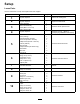
Maintenance Note: Determine the left and right sides of the machine from the normal operating position. Recommended Maintenance Schedule(s) Maintenance Service Interval Before each use or daily Maintenance Procedure • Clean the suction strainer. (More often when using wettable powders) Every 50 hours • Lubricate the pump. Every 100 hours • Lubricate the grease fittings. • Lubricate the boom hinges. Every 200 hours • Inspect all hoses and connections for damage and proper attachment.
Maintenance Check Item For the week of: Mon. Tues. Wed. Thurs. Fri. Sat. Sun. Check toe-in. Lubricate all grease fittings.1 Touch up and damaged paint. 1Immediately after every washing, regardless of the interval listed Notation for Areas of Concern Inspection performed by: Item Date Information 1 2 3 4 5 6 7 8 9 10 CAUTION If you leave the key in the ignition switch, someone could accidently start the engine and seriously injure you or other bystanders.
Figure 45 Left side shown 1. Front mounting bracket 4. Washer (1/2 inch) 2. Hold-down bracket 5. Locknut (1/2 inch) 3. Bolt (1/2 x 1-1/2 inches) Figure 47 1. Bed support 4. Fold the boom extensions forward, alongside the tank assembly to distribute the weight more evenly and keep it from tipping back. 3. Bed 2. Cylinder barrel 5. Raise the tank assembly until the lift cylinders are fully extended. Lowering the Tank Assembly 1.
Lubrication Greasing the Boom Hinges Service Interval: Every 100 hours Greasing the Sprayer System Important: If the boom hinge is washed with water, all water and debris must be cleared from the hinge assembly and fresh grease must be applied. Service Interval: Every 50 hours Every 100 hours Grease Type: No. 2 general-purpose lithium base grease. Lubricate all bearings and bushings after every 100 hours or once a year, whichever occurs first. 1.
1 8. Repeat the procedure for each actuator rod bearing. 4 2 5 3 G002016 Figure 50 1. Actuator 2. Actuator rod 3. Boom pivot pin housing 4. Cotter 5. Pin 3. Lift up on the boom and remove the pin (Figure 50). Slowly lower the boom to the hardstop. 4. Inspect the pin for any damage, replace if necessary. 5. Manipulate the actuator rod bearing end and apply grease into the bearing (Figure 51). Wipe off excess grease. Figure 51 Right boom 1. Grease bearing 6.
Electrical System Maintenance Spray System Maintenance WARNING Fuses Chemical substances used in the spray system may be hazardous and toxic to you, bystanders, animals, plants, soils or other property. • Carefully read and follow the chemical warning labels and Material Safety Data Sheets (MSDS) for all chemicals used and protect yourself according to the chemical manufacturer's recommendations.
necessary. (see an Authorized Toro Service Distributor) DANGER Use of the manual relief valve may cause the boom to move suddenly and cause injury to you or others. • Take caution and adjust the manual relief valve slowly. • Ensure the surrounding area is clear and no one is inside the operating range of the boom. Every 400 hours/Yearly (whichever comes first)—Inspect the pump check valves and replace if necessary.
Cleaning 3. Once the original position of the actuator is recovered, close the manual relief valve. Torque the valve to 1.1-2.1 ft-lb (1.5-2.9 N⋅m). Cleaning the Flowmeter Inspecting the Nylon Pivot Bushings Service Interval: Every 200 hours/Yearly (whichever comes first) (More often when using wettable powders) Service Interval: Every 400 hours/Yearly (whichever comes first) 1. Thoroughly rinse and drain the entire spraying system. 2.
Storage 2. Remove the retainer from the red fitting attached to the large hose on the top of the tank (Figure 55). 1. Position the sprayer on a level surface, set the parking brake, disengage the PTO, stop the engine, and remove the ignition key. 2. Clean dirt and grime from the entire machine, including the outside of the engine's cylinder head fins and blower housing. Important: You can wash the machine with mild detergent and water. Do not use high pressure water to wash the machine.
E. Clean the pistons and replace any worn O-rings. F. G. frame. This prevents the assembly from shifting when the fasteners securing the tank assembly to the frame are loosened. Coat all piston O-rings with vegetable oil and reinstall in the valve assembly with the screws previously removed. Make sure to install the springs into the valve assembly. 2. Lower booms to approximately 45° and then pivot them forward. Secure the valve seats to the valve assembly with the 3 forks previously removed. 3.
Troubleshooting Troubleshooting the Spray System Problem A boom section does not spray. Possible Cause Corrective Action 1. The electrical connection on the boom valve is dirty or disconnected. 1. Turn the valve off manually. Disconnect the electrical connector on the valve and clean all leads, then reconnect it. 2. Blown fuse 2. Check the fuses and replace them as necessary. 3. Repair or replace the hose. 4. Adjust the boom by-pass valves. 3. Pinched hose 4.
Problem The Area is inaccurate. The Distance is inaccurate. The monitor does not display Application Rate or Total Volume. The Total Volume is inaccurate. Possible Cause Corrective Action 1. The sprayer width is not correctly entered. 1. Check and set the appropriate Width in the calibration mode. 2. The speed sensor is not calibrated correctly. 3. The speed sensor is damaged. 2. Calibrate the speed sensor. 1. The speed sensor is not calibrated correctly. 1. Calibrate the speed sensor. 2.
Schematics G011797 Electrical, spray system (Rev.
Notes: 50
Notes: 51
The Toro Total Coverage Guarantee A Limited Warranty Conditions and Products Covered The Toro Company and its affiliate, Toro Warranty Company, pursuant to an agreement between them, jointly warrant your Toro Commercial product (“Product”) to be free from defects in materials or workmanship for two years or 1500 operational hours*, whichever occurs first. This warranty is applicable to all products with the exception of Aerators (refer to separate warranty statements for these products).